RWF ROTARY SCREW COMPRESSOR UNITS
MAINTENANCE
S70-600 IOM
Page 29
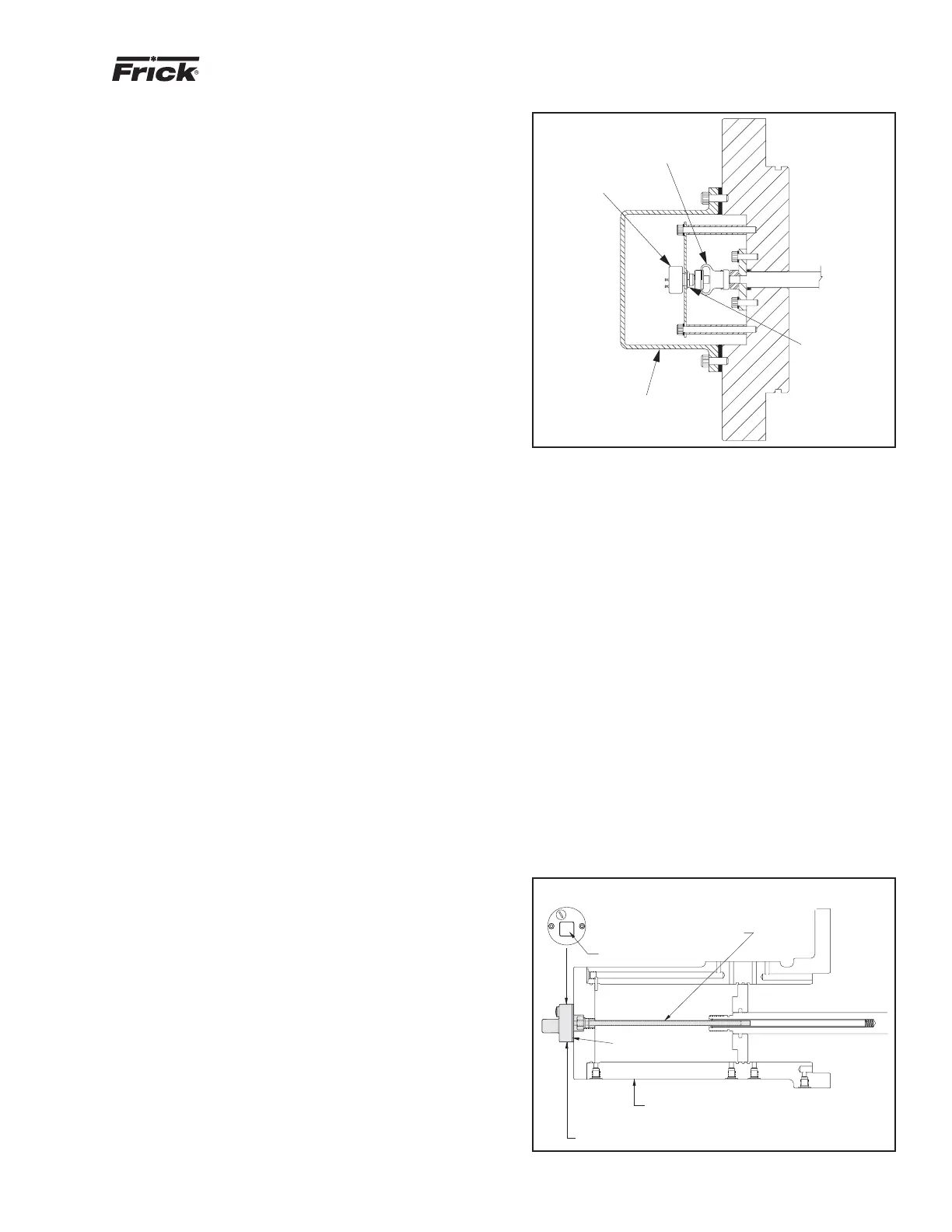
SV POSITION POTENTIOMETER
REPLACEMENT AND ADJUSTMENT
The Slide Valve Position potentiometer is located on the
end of the compressor unloader cylinder (applies to mod-
els 100 - 270), see Figure 23.
1. Shut off control power.
2. Remove the four socket head cap screws securing the
potentiometer cover to the unloader cylinder.
3. Unsolder leads to the potentiometer and remove.
4. Loosen the setscrew on the potentiometer side of the flex-
ible coupling.
5. Remove the three retainer clips securing the potentiometer
to the base plate. The potentiometer should slip out of the
coupling.
6. Install the new potentiometer and reassemble.
7. Adjustment:
ROUGH ADJUSTMENT is made with the slide valve fully
unloaded and the control power off. Remove connector P5.
With a digital voltmeter, measure the resistance across the
red and white wires, having removed them from the SBC.
The resistance should be 1000 +/- 50 ohms. If adjustment is
necessary, loosen the locknut and rotate the potentiometer
clockwise or counterclockwise until the resistance reading
is a close to a 1000 ohms as possible. Retighten the locknut
and replace wires. NOTE: Mechanical travel of the slide
valve potentiometer is 300 degrees rotation when the
slide stop is confirmed to be in the 2.2 Vi position. The
travel will be less than 300 degrees if the slide stop is in
any position above 2.2 Vi.
FINE ADJUSTMENT must be made with the slide valve fully
unloaded and the compressor running. The Operating dis-
play at this time should indicate a slide valve position of 0%. If
the display is greater than 0%, adjust potentiometer POT #4
on the SBC until 0% is indicated. If 0% is not attainable, get
as close as possible and then proceed to the next step. The
adjustments of POT #4 and POT #3 are interactive and POT
#3 may require adjustment to allow POT #4 to come into range.
Completely load the slide valve. The display at this time should
indicate 100%. If the display is less than 100%, adjust poten-
tiometer POT #3 on the SBC until 100% is indicated.
Repeat this sequence until the slide valve indicates 0% fully
unloaded and 100% fully loaded.
Figure 23
CAPACITY LINEAR TRANSMITTER
REPLACEMENT - SLIDE VALVE
The Capacity Linear Transmitter is located on the end of the
compressor unload cylinder (applies to models 100 - 270),
see Figure 24.
The linear transmitter with hermetic enclosure is based on
the inductive measuring principle. It features removable elec-
tronics (from the sensor well) eliminating the need to evacu-
ate the compressor for replacement. This type of transmitter
is dedicated to capacity control and is not adjustable.
1. Shut off control power.
2. Remove DIN connector plug from transmitter.
3. Loosen cap screws.
4. Remove transmitter unit.
5. Install new transmitter unit.
6. Tighten cap screws.
7. Apply DIN connector plug to transmitter.
8. Turn on control power.
POTENTIOMETER
FLEXIBLE
COUPLING
COVER
LOCKNUT
END VIEW
DIN CONNECTOR
STAINLESS STEEL WELL
HEAT ISOLATOR
CAST ALUMINUM HOUSING
COMPRESSOR UNLOAD CYLINDER
SHADED AREA SHOWS
CAPACITY LINEARTRANSMITTER
Figure 24