RWF ROTARY SCREW COMPRESSOR UNITS
MAINTENANCE
S70-600 IOM
Page 30
VOLUMIZER
®
TRANSMITTER
REPLACEMENT - SLIDE STOP
The VOLUMIZER
®
Transmitter is located on the right side of
the compressor (facing shaft) at the inlet end (see Figure 25).
The linear transmitter with hermetic enclosure is based on
the inductive measuring principle. It features removable elec-
tronics (from the sensor well) eliminating the need to evacu-
ate the compressor for replacement. This type of transmitter
is dedicated to volume ratio control and has no user adjust-
ments.
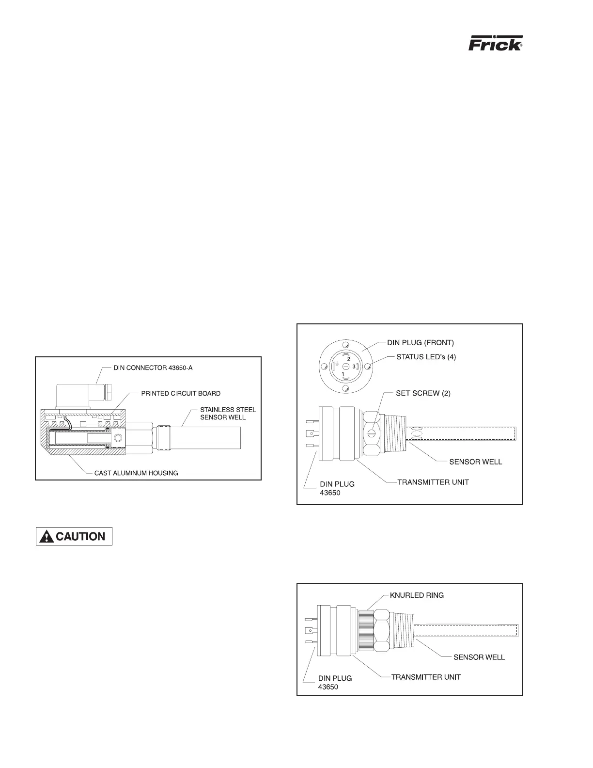
1. Shut off control power.
2. Remove DIN connector plug from transmitter.
3. Loosen set screws.
4. Remove transmitter unit.
5. Install new transmitter unit.
6. Tighten set screws.
7. Apply DIN connector plug to transmitter.
8. Turn on control power.
NOTE: For calibration of the Volumizer
®
unit, refer to the
Analog Calibration instructions in publication S90-010 O.
Figure 25 - VOLUMIZER
®
TRANSMITTER
TEMPERATURE SENSOR REPLACEMENT
This device is static sensitive.
Please follow proper ESD proce-
dures when handling.
1. Shut off control power.
2. Remove DIN connector plug from transmitter (See Figure
27).
3. Unscrew knurled ring and remove transmitter unit.
4. Apply thermal compound to new sensor assembly, insert
into thermal well, and tighten knurled ring.
5. Apply DIN connector plug to transmitter.
6. Turn on control power.
NOTE: The temperature sensor is factory set. If calibra-
tion is required, refer to Analog Calibration instructions
in publication S90-010 O.
OIL LEVEL TRANSMITTER
REPLACEMENT
The Oil Level Transmitter is located on the front of the sepa-
rator near the bottom/center (see Figure 26).
The linear transmitter with hermetic enclosure is based on
the capacitive measuring principle. It features removable
electronics (from the sensor well) eliminating the need to
evacuate the compressor for replacement. This transmitter
is dedicated to oil level control and has no user adjustments.
1. Shut off control power.
2. Remove DIN connector plug from transmitter.
3. Loosen set screws.
4. Remove transmitter unit.
5. Install new transmitter unit.
6. Tighten set screws.
7. Apply DIN connector plug to transmitter.
8. Turn on control power.
Figure 26 - OIL LEVEL TRANSMITTER
Figure 27 - TEMPERATURE TRANSMITTER