RWF ROTARY SCREW COMPRESSOR UNITS
PROPER INSTALLATION OF ELECTRONIC EQUIPMENT
S70-600 IOM
Page 44
PROPER INSTALLATION OF ELECTRONIC EQUIPMENT
IN AN INDUSTRIAL ENVIRONMENT
In today’s refrigeration plants, electronic controls have found
their way into almost every aspect of refrigeration control.
Electronic controls have brought to the industry more pre-
cise control, improved energy savings and operator conve-
niences. Electronic control devices have revolutionized the
way refrigeration plants operate today.
The earlier relay systems were virtually immune to radio fre-
quency interference (RFI), electromagnetic interference
(EMI), and ground loop currents. Therefore installation and
wiring were of little consequence and the wiring job con-
sisted of hooking up the point-to-point wiring and sizing the
wire properly. In an electronic system, improper installation
will cause problems that outweigh the benefits of electronic
control. Electronic equipment is susceptible to RFI, EMI, and
ground loop currents which can cause equipment shutdowns,
processor memory and program loss, erratic behavior, and
false readings. Manufacturers of industrial electronic equip-
ment take into consideration the effects of RFI, EMI, and
ground loop currents and incorporate protection of the elec-
tronics in their designs. These manufacturers require that
certain installation precautions be taken to protect the elec-
tronics from these effects. All electronic equipment must be
viewed as sensitive instrumentation and therefore requires
careful attention to installation procedures. These procedures
are well known to instrument engineers, but are usually not
followed by general electricians.
There are a few basics, that if followed, will result in a trouble-
free installation. The National Electric Code (NEC) is a guide-
line for safe wiring practices, but it does not deal with proce-
dures used for electronic control installation. Use the fol-
lowing procedures for electronic equipment installation.
These procedures do not override any rules by the NEC, but
are to be used in conjunction with the NEC code.
WIRE SIZING
Size supply wires one size larger than required for am-
perage draw to reduce instantaneous voltage dips
caused by large loads such as heaters and contactors
and solenoids. These sudden dips in voltage can cause
the processor, whether it be a microprocessor, a computer,
or a PLC to malfunction momentarily or cause a complete
reset of the control system. If the wire is loaded to its maxi-
mum capacity, the voltage dips are much larger, and the
potential of a malfunction is very high. If the wire is sized
one size larger than required, the voltage dips are smaller
than in a fully loaded supply wire, and the potential for mal-
function is much lower. The NEC code book calls for specific
wire sizes to be used based on current draw. An example of
this would be to use #14 gauge wire for circuits up to 15
amp or #12 gauge wire for circuits of up to 20 amp. There-
fore, when connecting the power feed circuit to an electronic
industrial control, use #12 gauge wire for a maximum cur-
rent draw of 15 amp and #10 wire for a maximum current
draw of 20 amp. Use this rule of thumb to minimize voltage
dips at the electronic control.
VOLTAGE SOURCE
Selecting the voltage source is extremely important for proper
operation of electronic equipment in an industrial environ-
ment. Standard procedure for electronic instrumentation is
to provide a “clean” separate source voltage in order to
prevent EMI, from other equipment in the plant, from inter-
fering with the operation of the electronic equipment. Con-
necting electronic equipment to a breaker panel (also known
as lighting panels and fuse panels) subjects the electronic
equipment to noise generated by other devices connected
to the breaker panel. This noise is known as electromag-
netic interference (EMI). EMI flows on the wires that are
common to a circuit. EMI cannot travel easily through trans-
formers and therefore can be isolated from selected circuits.
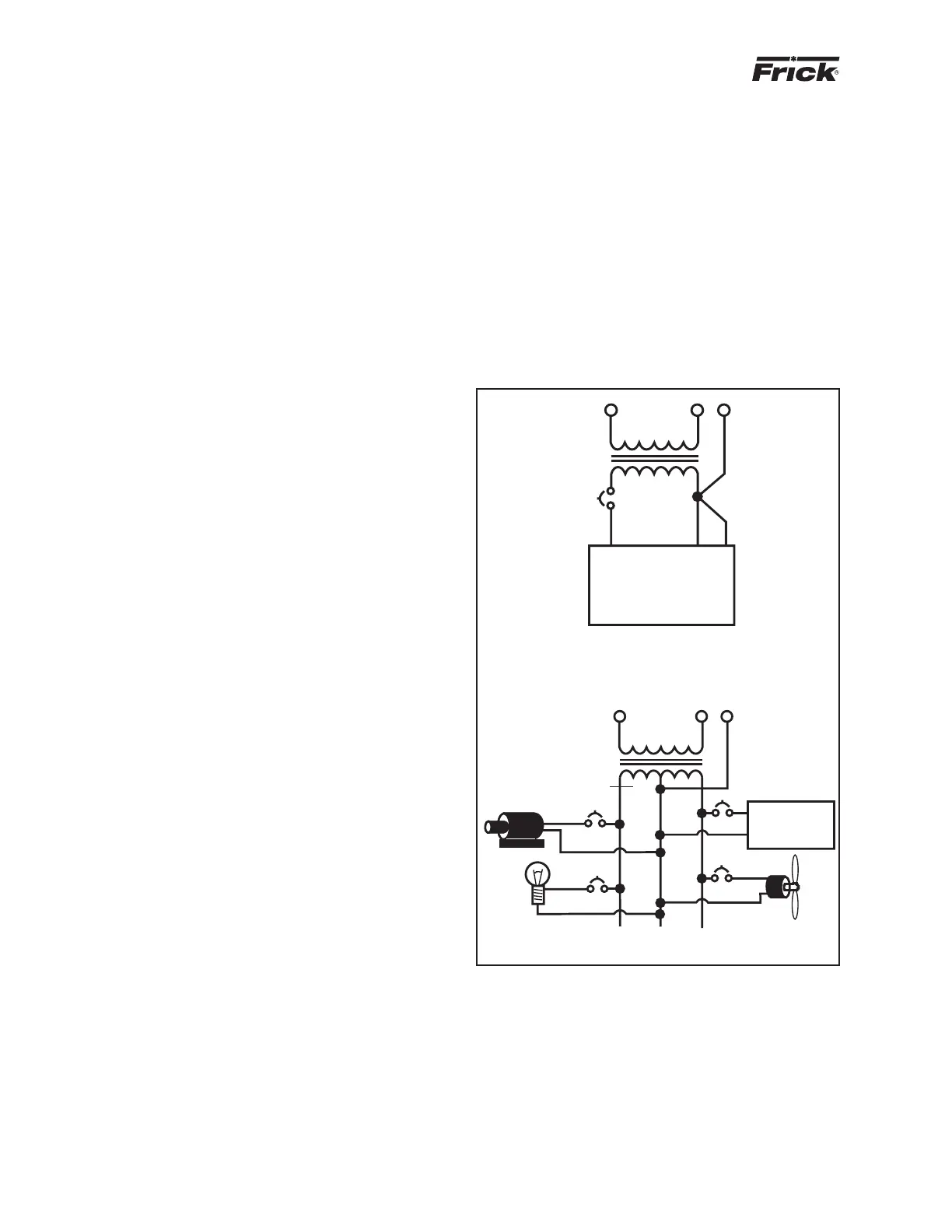
Use a control transformer to isolate the electronic con-
trol panel from other equipment in the plant that gener-
ate EMI. (Figure 1)
CONTROL
TRANSFORMER
ISOLATED
CIRCUIT
GROUND
ELECTRONIC CONTROL
CORRECT
ART1T
CONTROL
TRANSFORMER
NONISOLATED
CIRCUIT
GROUND
ELECTRONIC
CONTROL
INCORRECT
ART1B
Figure 1