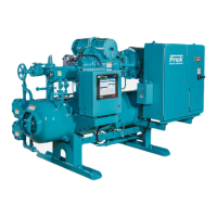
RWF ROTARY SCREW COMPRESSOR UNITS
OPERATION
S70-600 IOM
Page 15
COMPRESSOR OIL COOLING SYSTEMS
The RWF unit can be equipped with one of several systems
for controlling the compressor oil temperature. They are
single or dual-port liquid injection and thermosyphon or
water-cooled oil coolers. Each system is automatically con-
trolled, independent of compressor loading or unloading.
Oil cooling systems should maintain oil temperature within
the following ranges for R-717 and R-22:
Liquid Injection External*
Oil Cooling Oil Cooling
R-717 130 - 170°F 120 - 140°F
R-22 130 - 150°F
* Thermosyphon oil cooling (TSOC) or Water cooled oil cool-
ing (WCOC).
SINGLE-PORT LIQUID INJECTION
The single-port liquid injection system is designed to per-
mit liquid refrigerant injection into one port on the compres-
sor at any given moment and operates as outlined.
Solenoid valve YY5 is energized by the microprocessor when
the temperature sensor, installed in the oil manifold, exceeds
the LICO set point. High-pressure liquid refrigerant is then
supplied to the temperature control valve (TCV). The tem-
perature control valve is equalized to a constant back pres-
sure by the differential pressure control valve (PDCV). The
differential pressure control valve uses discharge gas to
maintain downstream pressure. The gas downstream of the
differential pressure control valve is bled off to the compres-
sor suction to ensure steady and constant operation of the
valve. Refer to P & I DIAGRAMS section for piping and
instrumentation drawings.
BOOSTER OR SWING DUTY APPLICATION
Discharge gas from the high-stage compressor is required
to assist the differential pressure control valve (PDCV) in
providing the temperature control valve (TCV) with a con-
stant back pressure.
A solenoid valve YY6 is installed before the differential pres-
sure control valve (PDCV) to prevent migration of high pres-
sure gas during shutdown. A Frick-installed timer limits the
high pressure gas to only thirty seconds duration, since in-
termediate gas pressure and spring tension are sufficient to
maintain closure on unit shutdown. A metering valve is also
provided for use as a service valve and to allow discharge
gas flow regulation to prevent excessive force and resulting
closure “hammering”.
A field-installed 1/4 inch OD tubing connection is required
between the high stage compressor discharge piping line
(or receiver) and the check valve. Refer to P & I DIAGRAMS
section for piping and instrumentation drawings.
NOTE: An oil pump may be required for booster or swing
duty applications.
DUAL-PORT LIQUID INJECTION
The dual-port liquid injection system is designed to obtain
the most efficient compressor performance at high and low
compression ratios by permitting injection of liquid refriger-
ant into one of two ports optimally located on the compressor.
This minimizes the performance penalty incurred with liquid
injection oil cooling.
The dual-port system contains all the components of the
single-port system with the addition of a double acting sole-
noid valve YY7 and operates as outlined.
Solenoid valve YY5 is energized by the microprocessor when
the temperature sensor, installed in the oil manifold, exceeds
the LICO set point. Liquid refrigerant is then passed through
the temperature control valve (TCV) to the double-acting
solenoid valve YY7. Depending on the compressor’s oper-
ating volume ratio (Vi), the microprocessor will select the
flow of the liquid refrigerant to either compressor port SL-1
or SL-2, whichever is more efficient.
When the compressor operates BELOW 3.5 Vi, compressor
port SL-1 supplies the liquid cooling. When the (Vi) rises
ABOVE 3.5 Vi, port SL-2 supplies the liquid cooling.
The temperature control valve is equalized to a constant
back pressure by the differential pressure control valve
(PDCV).
Both the differential pressure control valve (PDCV) and the
double-acting solenoid valve YY7 use discharge gas to main-
tain downstream pressure. The gas downstream of both valves
is bled off to the compressor suction to ensure steady and
constant operation of the valves. Refer to P & I DIAGRAMS
section for piping and instrumentation drawings.
LIQUID INJECTION ADJUSTMENT
PROCEDURE
1. Close back-pressure bleed valve (V4).
2. Set pressure regulator valve (PDCV) for approximately
40 to 60 psig.
3. Open back-pressure bleed valve (V4) approximately one
quarter turn.
4. Monitor the oil temperature of the compressor. If the oil
temperature rises above 170
°
F, open back-pressure bleed
valve (V4) a very small amount. This will reduce pressure
on the equalizer and allow more refrigerant to flow to the
compressor. If the oil temperature drops below 150
°
F, close
back-pressure bleed valve (V4) a very small amount. This
will increase pressure on the equalizer and allow less re-
frigerant to flow to the compressor, thus raising the oil tem-
perature. The ideal condition is to maintain an oil tempera-
ture as stable as possible. By keeping the liquid injection
system correctly tuned, extreme swings in the discharge tem-
perature and the oil temperature can be avoided. Refer to
P & I DIAGRAMS section for piping and instrumentation
drawings.
Back-pressure bleed valve (V4)
must always be cracked open a
small amount to prevent refriger-
ant from condensing in the tubing.

 Loading...