27
C. INSTALLATION OF THE UNIT
C.6 Cord Routing Change
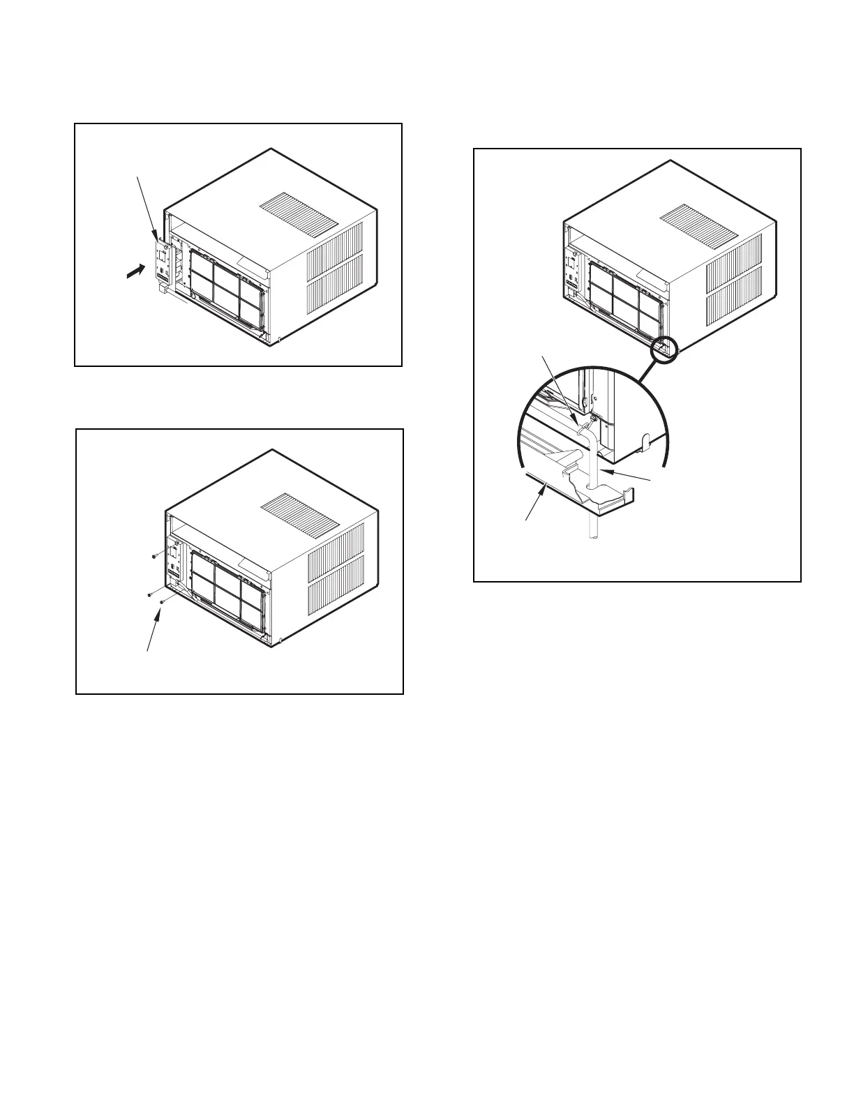
STEP 5. Carefully push electrical control panel back into chassis.
Figure C.6.6
ELECTRICAL
CONTROL PANEL
STEP 6. Reinstall the 3 screws removed earlier to secure electrical
control panel.
Figure C.6.7
ELECTRICAL CONTROL PANEL SCREWS (3)
(RETAINED FROM STEP 1)
STEP 7. If running power cord to the right of the unit, install the cord into
the cord retainer clips along the bottom front of the unit.
CORD RETAINER
CLIPS
POWER
CORD
FRONT
GRILLE
Figure C.6.6