24 PB
OPERATION
Remote Wall Thermostat
All Friedrich Vert-I-Pak units are factory congured to be controlled by using a single stage heat/cool remote wired wall
mounted thermostat.
Thermostat Selection
SINGLE STAGE THERMOSTATS
RT7P
Wired, single stage, wall-mounted programmable thermostat with two fan speeds
and backlight. Controls Friedrich VERT-I-PAK.
RT7
Wired, single stage, wall-mounted digital thermostat with two fan speeds and
backlight. Controls Friedrich VERT-I-PAK.
WRT2
Wireless, single stage, wall-mounted programmable thermostat with two fan
speeds and backlight. Controls Friedrich VERT-I-PAK.
ENERGY MANAGEMENT THERMOSTATS
EMRT2/EMWRT2
Wired/Wirelss thermostat with occupancy sensor
Thermostat terminals requirements:
C, R, G, Y, W, B.
For two fan speeds, thermostat must have 2 fan speed selection.
During Heat Mode:
The B terminal must be continuously energized. The W terminal must have 24 VAC output to call for heat. The control board
decides on whether to turn on the Heat Pump Heat (compressor) or Electric Heat. The Y terminal should not have 24 VAC output
during heat mode.
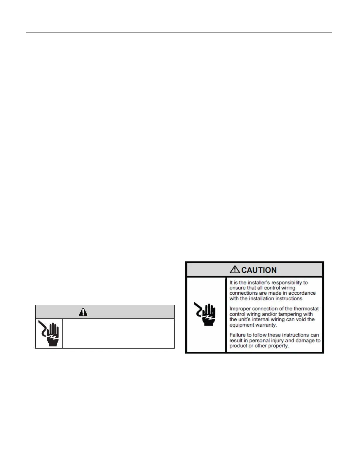
Connecting a Remote Wall Thermostat
WARNING
ELECTRIC SHOCK HAZARD
Disconnect power to the unit before
servicing. Failure to follow this warning
could result in serious injury or death.
1) Ensure jumper Is not Installed At FP And F2
2) Disconnect power to the unit.
3) Unscrew and remove the electrical control box’s cover.
4) Locate the Interface Connector (24 VAC terminal strip (See gure 1 at left).
5) Make the wire connections according to the con guration needed for
your unit Use #18 gauge wire size.
6) Once each wire is matched and connected, the unit is now ready to be controlled by the thermostat.
7) Reattach the electrical control box’s cover.
CONNECT THERMOSTAT USING FIGURES 301, 302, and 303.
Refer to thermosts Manuals for installation. Current thermo-
stat manuals may be obtained online at www.friedrich.com.
 Loading...