25 PB
OPERATION
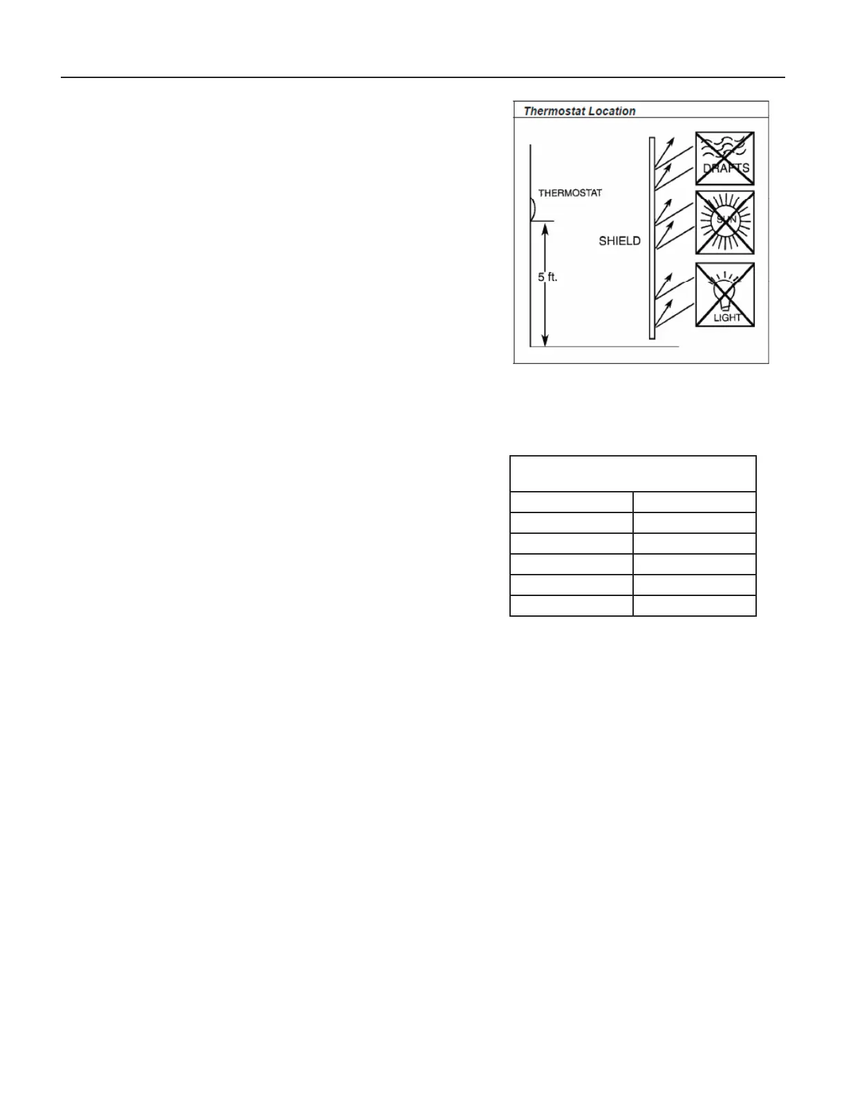
Remote Wall Thermostat Location
The thermostat should not be mounted where it may be affected by drafts,
discharge air from registers (hot or cold), or heat radiated from the sun
appliances, windows etc.. The thermostat should be located about 5 Ft. above
the oor in an area of average temperature, with good air circulation.
Mercury bulb type thermostats MUST be level to control temperature
accurately to the desired set-point. Electronic digital type thermostats should
be level for aesthetics.
Note: An improperly operating or poorly located remote wall thermostat
can be the source of perceived equipment problems. A careful check of the
thermostat’s location and wiring must be made then to ensure that it is not the
source of problems.
Desk Control
The unit’s electronic control has built-in provisions for connection to an exter-
nal switch to control power to the unit. The switch can be a central desk control
system or even a normally open door switch.
For desk control operation, connect one side of the switch to the D1 terminal and the
other to the D2 terminal (See page 12). Whenever the switch closes, the unit operation
will stop.
Maximum wire Length for Desk Control
Switch
Wire Size Maximum Length
#24 400 ft.
#22 600 ft.
#20 900 ft.
#18 1500 ft.
#16 2000 ft.
Auxiliary Fan Control
The electronic control also has the ability to control a 24 VAC relay to activate an auxiliary, or transfer fan. The outputs are
listed as F1 and F2 on the interface connector (See page 12).
To connect the relay, simply wire one side of the relay to F1 and the other side to F2. Anytime that the fan runs, the terminals
will send a 24 VAC signal to the relay. The relay must be 24 VAC, 50mA or less.
Note: The Desk Control, Auxiliary Fan relay and wires must be eld supplied.
Figure 303 (Thermostat Locations)
 Loading...