37 PB
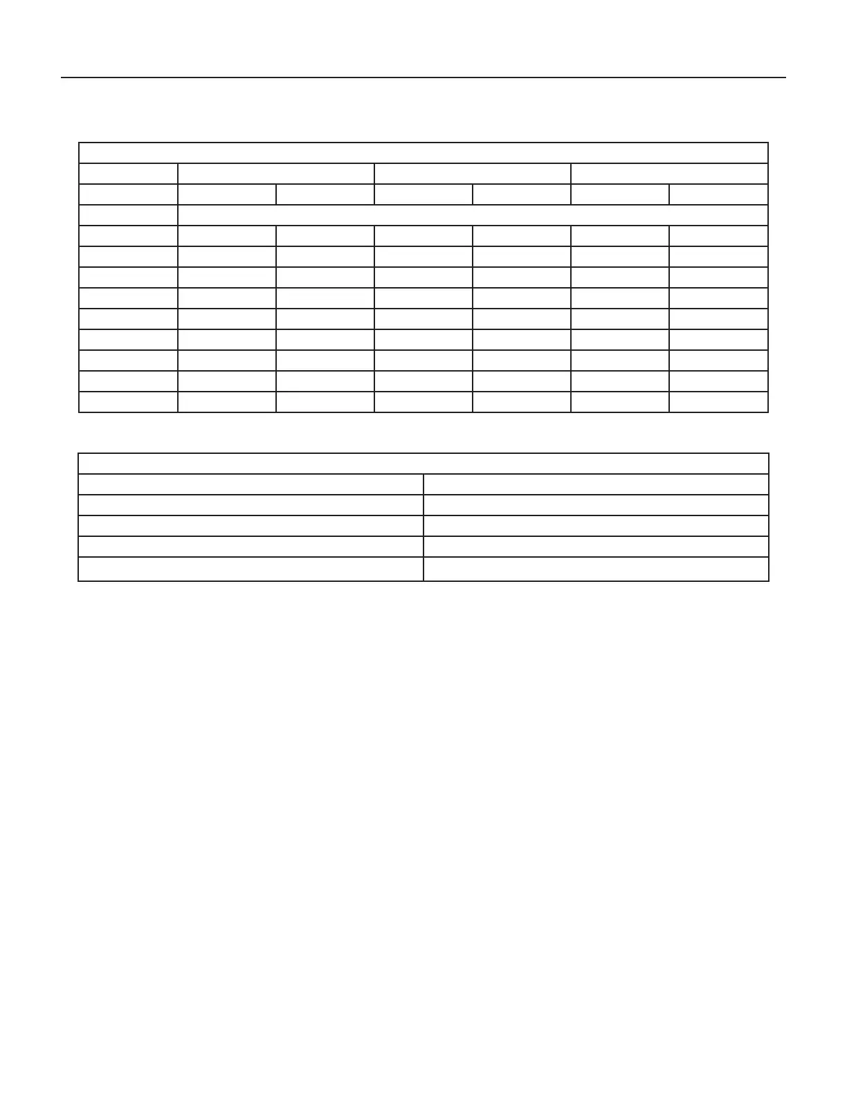
External Static Pressure
Determining the Indoor CFM
MODEL VHA 09/12 VHA 18 VHA 24
FAN SPEED LOW HIGH LOW HIGH LOW HIGH
ESP (“) CFM
0.0” 470 520 730 800 755 805
0.05” 460 510 670 735 700 750
0.10” 430 490 630 675 660 700
0.15” 410 470 595 640 615 665
0.20” 360 440 550 600 575 625
0.25” 310 400 505 550 525 580
0.30” 260 350 455 500 485 540
0.35” -- -- 400 445 450 500
0.40” -- -- 345 400 415 465
* values indicate rated performance point
Table XXX (determining Indoor CFM)
Correct CFM (if needed): Correction Multipliers
230V 1.00
208V 0.97
265V
Heating 1.00
Cooling 0.95
Explanation of charts
Chart A is the nominal dry coil VERT-I-PAK CFMs. Chart B is the correction factors beyond nominal conditions.
1 ½ TON SYSTEM ( 18,000 Btu)
Operating on high speed @ 230 volts with dry coil
measured external static pressure .10
Air Flow = 450 CFM
In the same SYSTEM used in the previous example but having a WET coil you must use a correction factor of .95 (i.e. 450 x
.95=428 CFM) to allow for the resistance (internal) of the condensate on the coil.
It is important to use the proper procedure to check external Static Pressure and determine actual air ow. Since in the case
of the VERT-I-PAK, the condensate will cause a reduction in measured External Static Pressure for the given air ow.
It is also important to remember that when dealing with VERT-l-PAK units that the measured External Static Pressure in-
creases as the resistance is added externally to the cabinet. Example: duct work, lters, grilles.
Indoor Airow Data
The Vert-I-Pak A series units must be installed with a free return air conguration. The table below lists the indoor airow at
corresponding static pressures. All units are rarted at low speed.
The Vert-I-Pak units are designed for either single speed or two fan speed operation. For single speed operation refer to the
airow table below and select the most appropriate CFM based on the ESP level. Connect the fan output from the thermostat
to the unit on either the GL terminal for low speed or to the GH terminal for high speed operation.
For thermostats with two-speed fan outputs connect the low speed output to the unit GL terminal and the high speed output
to the GH terminal.
Ductwork Preparation
If ex duct is used, be sure all the slack is pulled out of the ex duct. Flex duct ESP can increase considerably when not fully
extended. DO NOT EXCEED a total of .30 ESP, as this is the MAXIMUM design limit for the VERT-I-PAK A-Series unit.
IMPORTANT: FLEX DUCT CAN COLLAPSE AND CAUSE AIRFLOW RESTRICTIONS. DO NOT USE FLEX DUCT FOR: 90 DEGREE
BENDS, OR UNSUPPORTED RUNS OF 5 FT. OR MORE.
 Loading...