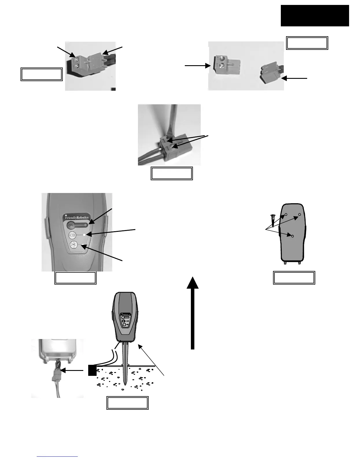
Figure 1.15
Male
Female
Male- to
perimeter wire
Perimeter Switch
connectors unfastened
Chapter 1
Page 15
Female side-
to Perimeter
Switch
Perimeter Switch
connectors attached
Figure 1.16
Female- to
Perimeter
Switch
Using a small flat blade
screwdriver, tighten these
two screws to secure the
perimeter wires into the
connecto
Strip back ¼ inch (6 mm) of insulation
from each wire end and insert each
perimeter wire end into hole of
connector.
Figure 1.17
On button and
indicator light
Low battery
indicator light
Disconnected/broken
wire indicator light
Figure 1.18
Mounting the Perimeter
Switch using three
mounting bosses on
back cover
Figure 1.20
Perimeter Switch with
mounting stake attached.
Disconnect Perimeter Switch
connector and move switch to
new plot.
Chapter 1
Page 19
Figure 1.19
The Perimeter Switch MUST be mounted
vertically in order to maintain its’ water
resistance