INSTALLATION AND SERVICE MUST BE PERFORMED BY
A QUALIFIED INSTALLER.
IMPORTANT: SAVE FOR LOCAL ELECTRICAL INSPECTOR'S USE.
READ AND SAVE THESE INSTRUCTIONS FOR FUTURE REFERENCE.
if the information in this manual is not followed exactly, a fire or explosion may
result causing property damage, personal injury or death.
FORYOUR SAFETY:
-- Do not store or use gasoline or other flammable vapors and liquids in the vicinity of this or any other
appliance.
-- WHATTO DO IFYOU SMELLGAS:
• Do nottrytolightanyappliance.
• Do not touch any electrical switch; do not use any phone in your building.
• Immediately call your gas supplier from a neighbor's phone. Follow the gas supplier's instructions.
• If you cannot reach your gas supplier, call the fire department.
-- Installation and service must be performed by a qualified installer, service agency or the gas supplier.
Do not pinch the power supply cord or the flexible gas
conduit between the range and the wall.
Do not seal the range to the side cabinets.
**NOTE: 30" (76.2 cm) minimum clearance between the
cooktop and the bottom of the cabinet when the bottom
of wood or metal cabinet is protected by not less than F4"
(0.64 cm) flame retardant millboard covered with not less
than No. 28 MSG sheet metal, 0.015" (0.4 rnm)stainless
steel, 0.024" (0.6 mrn) aluminum, or 0.020" (0.5 mrn)
copper.
Shave Raised Edge
to Clear 30" Min. 13"
31 1/2" (81 cm) 76.2 crn Min. (33 cm)
Wide Cooktop Rim
1 Y_" Max.
(13.8crn Max.) Min.)
From Wall "q,
18" Min.
(45.7 cm) Min.
36" (91.4 cm) minimum clearance when the cabinet is
unprotected.
• NOTE: Allow at
least 19 F4" (48.9
crn) clearance for
door depth when
it is open.
S
• Door Open
(see
jJJ_i
C ¸
jJ
z
_" 15/16"
_,21 3/4" _W/ (3.33 cm)
_/55.5 cm/ .......
A
? 2
g lator
._ . ....
B
Locate Cabine
Doors 1" (2.5
crn) Min.
from Cutout
Opening.
* Note: For 29" (73.7
crn) cutout wide
opening, you must call
for optional side
panels and clear wide
cooktop rim as shown
in the "Countertop
Preparation" section
(see page 3).
i¸¸ I iL
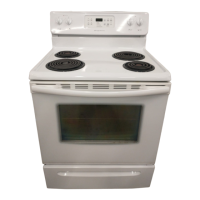
A HE GHT BIWIDTH
35 318" (90 cm) 30"
36 3/8" (92 cm) (76,2 cm)
Grounded rction Box or Wall
Outlet Should Be Located 8" to
17" (20.3 cm to 43.2 cm) From
Right Cabinet and 2" to 4" (5.1
crn to 10.2 cm) From Floor.
C. DEPTH F.MINIMUM IS cuToUT ' H HEIGHT
TO FRONT CUTOUT ' " _
OF RANGE WDTH DEPTH couN_mToP
28 5/16" 30" 21 3/4" (55,2 crn) Min. 36" (91,4 crn) standard
(71,9 crn) (76,2 cm) 22 1/8" (56,2 cm) Max. 35 3/8" (90 crn) rnin.
--e
FRONT
OF
CABINET
24" Min.
(61 crn Min.
22 7/8" *
(58.1 crn)rnin.
__ 23 1/4"*
__1 1/8"
(2.86 crn)
Ref.
G. Minimum Cutout Depth is increased to 24" (61 cm) with backguard.
NOTE: Wiring diagram for these appliances are enclosed in this booklet.
¢-_ Recycled paper
* For cutouts be ow 22 7/8", appli_ nce
will slightly show out of the cabinet.
P/N 318201663 (0305) Rev. A
Installation instructions - pages 1-9
Wiring Diagram - page 10