21
EN
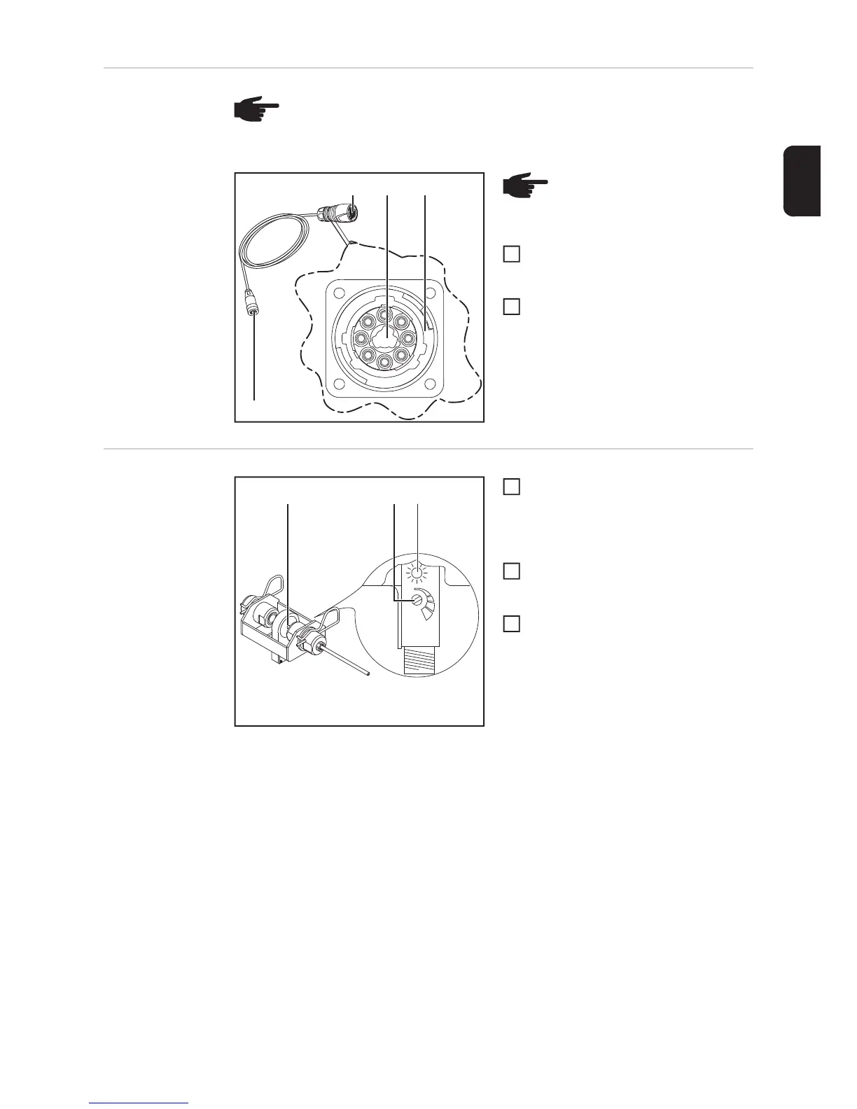
Connecting the
sensor
Connect the plug (1) on the connecting
cable to an OPT/i ext. sensor plug (2)
connection of the wirefeeder/SplitBox
Connect the plug (4) to the sensor
Adjusting the
OPT/i WF R wire
end ring sensor
Rotate the wire electrode in the
opening (1) of the sensor during the
entire adjustment process
- LED (3) lights up when the sensor
detects the wire electrode
Turn the adjusting screw (2) back until
the LED (3) goes out
- Wire sensor is deactivated
Slowly turn the adjusting screw (2) for-
wards again until the LED (3) lights up
- stop turning as soon as the LED lights
up
- The sensor is now set at its lowest
sensitivity level
- This prevents the wire sensor from
being triggered accidentally
NOTE! The wirefeeder/SplitBox recognises that there is a sensor connected to
the connecting cable. Each sensor is supplied with its own connecting cable,
which must be used. The sensor connecting cable will be marked with the item
number and name of sensor.
(3)(1) (2)
(4)
NOTE! The plug (1) of the con-
necting cable may only be con-
nected to the sensor connections
(2) that are colour-coded red (3).
1
2
(1)
(3)(2)
1
2
3
 Loading...