4
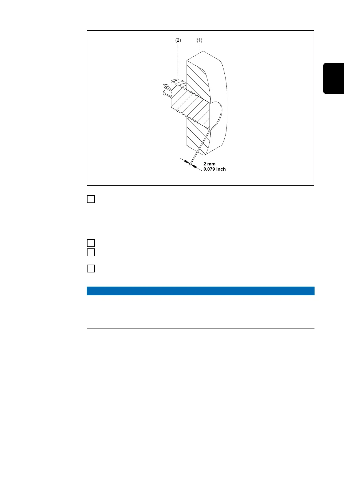
Unscrew the shoe (1) from the sensor (2), ensuring that the gap between the
sliding surface of the shoe and the surface of the sensor is 2 mm (0.079 inch)
If adjustment as described below is no longer possible, replace the shoe (1). -
see section Replacing wearing parts on page 28
5
Tighten nut (4)
6
Position the shoe (1) and sensor (2) on the retaining arm (3) and tighten using
two screws (5)
7
Unlock the retaining arm (3) and ensure that the shoe is touching the wire
electrode
NOTE!
Risk due to incorrect sensor positioning.
False triggers can be the result.
▶
Make sure, the retaining arm must not touch the wirespool or the wire elec-
trode.
27
EN-US
 Loading...