22
Controls, connections and mechanical components
General remarks The positions of the following controls, connections and mechanical components are cus-
tomer-specific and may vary.
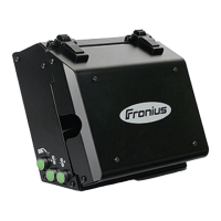
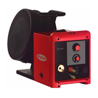
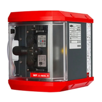
Front of wirefeed-
er
Front of VR 1500 / VR 1550 Front of VR 1500 - 11 / 12 / 30
(1) Blanking cover / gas pressure sensor adjusting button (optional)
(2) Water return connection (red)
(3) Gas test button
for setting the required gas flow rate on the pressure regulator. If you press and
hold this button, gas will flow.
(4) Wire threading button
for threading the wire electrode into the torch hosepack with no flow of gas or cur-
rent.
(5) Additional fan
(6) Robacta robot welding torch connection on VR 1500
(see circuit diagram X10 for pin assignment) or
Wire buffer connection on VR 1550 (CMT-WS) and VR 1550 CMT installation kit
(optional)
(7) Robacta robot welding torch connection on VR 1550 (CMT-WS)
(see circuit diagram X10 for pin assignment)
(8) Blanking cover/AIR IN "torch blow out" connection
(high end option, max. 15 bar) or
LHSB connection on VR 1550 (CMT-WS) and VR 1550 CMT installation kit (op-
tional)
(9) Water flow connection (black or blue)
(10) AIR OUT "torch blow out" connection (optional)
(11) Tuchel plug (optional)
(4)(3)
(12)
(9)
(6)
(2)
(8)
(1)
(7)
(13) (10)
(2)
(8) (6)(9)
(12)
(1)
(4)(3)
(10)(11) (5)(13)
 Loading...