Manual of Two-Way Radio System www.FrSky-rc.com P7of9
-Rx interface 2: Analog Port 2 on Rx;
-Rx interface 3: RSSI of Rx;
Note: The alarm threshold of Rx interface 1 and 2 could be set by user. Two
alarm thresholds and three levels alarm state are available for both of Rx interface
1 and 2.
And the RSSI alarm setting is default by factory.
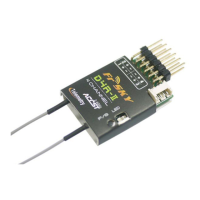
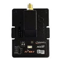
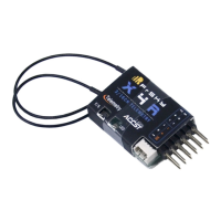
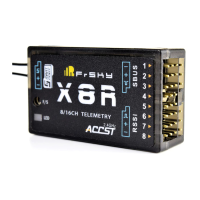
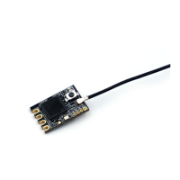
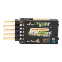
9.2 Pins Definition:
The Pin definition on receiver and Tx module:
It should be noted that the 3.3V voltage only have a limited driving current
(1~10mA), should not be used for driving a MPU.
RXD: input to receiver, RS232 level
AD2: Voltage: max 3.3V
AD1: Voltage: max 3.3V
Pins Definition at Rx Pins Definition at Tx
10. LED Status:
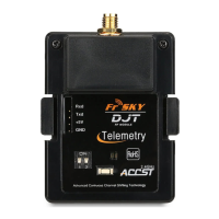
10.1 LED status on Transmitter module:
Red LED on and Green LED flashing: Working Mode.
Red LED off and Green LED flashing: Range Check Mode.
Red LED flashing: Binding Mode.