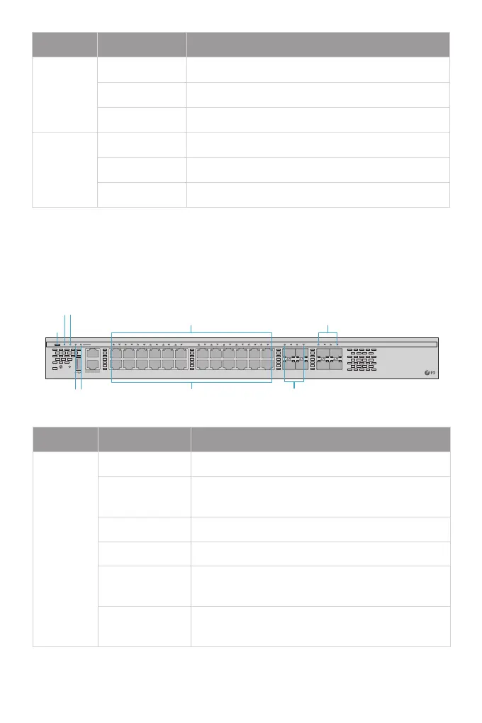
LEDs Status Description
MGMT
SYS PWR FAN
PoE
1 2
3
4
5
6 7 8
9 10
11 12
13 14 15 16 17 18 19 20 21 22
23 24
25 26
27 28
29 30
31 32
PoE FUNC
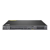
S5860-24XB-U
Green=10G/5G/2.5G/1G On=Link Flashing=ACT PoE LED Mode:Green=Good Supply Yellow=Over Load
CONSOLE
Yellow=100M
SFP+
O The SFP+ port is NOT connected.
Solid Green The SFP+ port is connected at 1/10G.
Blinking Green The SFP+ port is transmitting or receiving data at 1/10G.
QSFP28
O The QSFP28 port is NOT connected.
Solid Green The QSFP28 port isconnected at 40/100G.
Blinking Green The QSFP28 port is transmitting or receiving data at 40/100G.
Solid Green The system works properly.
Solid Yellow
Solid Blue
1. The temperature reaches the threshold value.
2. Dierent power modules are used together.
The locator takes eect. It is controlled by O&M personnel
remotely.
LEDs Status Description
O
Solid Red
The system is powered o.
Blinking Green Initialization is in progress.
1. A system fault occurs.
2. The temperature reaches the upper limit.
SYS
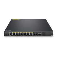
S5860-24XB-U
RJ45
PoE (1-24)
SFP+
SFP28
MGMT
SYS
PWR
FAN
PoE

 Loading...