COMPASS S2
TM
Quick Start Guide
COMPASS S2
TM
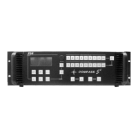
Connectivity Diagram
Illustration of Typical Compass S2™ Setup
Step 1: Connect Compass S2™ to Output Devices
Connect one of the two available “Main” video outputs to your projector and the “Main” audio output to a set of amplified speakers. Note
that the second main video output may be connected to a local display monitor if the projection screen is not easily viewed by the
operator.
Connect the “Preview” video output to a computer monitor and the “Preview” audio output to a second pair of powered
speakers. (Note: The preview video output timing is identical to the main video output. If the main video output is set to 1280 x 1024,
the preview monitor must be capable of that resolution.)
Step 2: Connect Input Sources to Compass S2™
Compass S2™ has eight universal video inputs that accept composite (NTSC & PAL), S-video, component, and computer video
sources. Connect each type of video input source to Compass S2™ as indicated in the following table:
Input Connections
Format – RGB
(Typical Devices: Computers)
Format – YUV or Y Pr Pb (Betacam)
(Typical Devices: DVD Player or Betacam Deck)
Source to Compass S2 Source to Compass S2
R R/CR Y G/Y
G G/Y Pr R/CR
B B/CB Pb B/CB
H H/C or
V V Y G/Y
U R/CR Format – S-Video (Y/C)
(Typical Devices: S-Video VCR)
V B/CB
Source to Compass S2
Format – Composite/PAL (Typical Devices: NTSC/PAL VCR)
Y G/Y
Source to Compass S2
C B/CB NTSC/PAL G/Y
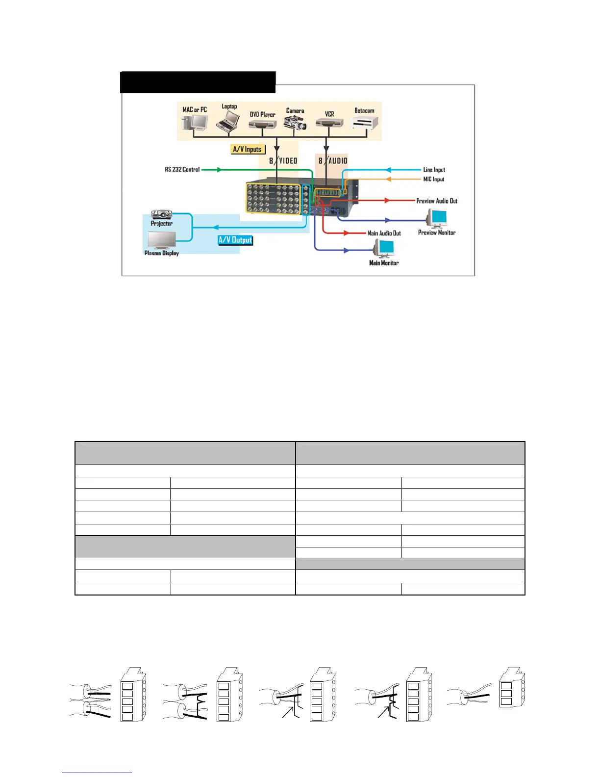
Compass S2™ has nine audio inputs that accept balanced and unbalanced signals for audio Sources 1 through 8 and a single Line
input. A tenth input accepts several types of microphones. Connect each type of audio input source to Compass S2™ as indicated in
the following diagram:
L
+
-
+
-
R
SH
Stereo Input Connector Wiring
L
+
-
+
-
R
SH
Balanced Wiring Unbalanced Wiring
Jumpers
L
+
-
+
-
R
SH
Mono Input Connector Wiring
L
+
-
+
-
R
SH
Balanced Wiring Unbalanced Wiring
Jumpers
Jumpers
Mic Input Connector
Wiring
+
-
SH