Fatigue Technology Inc. 401 Andover Park East Seattle, WA • USA 98188-7605 Tel: (206)246-2010 Fax: (206)244-9886
57429 – Rev L 17
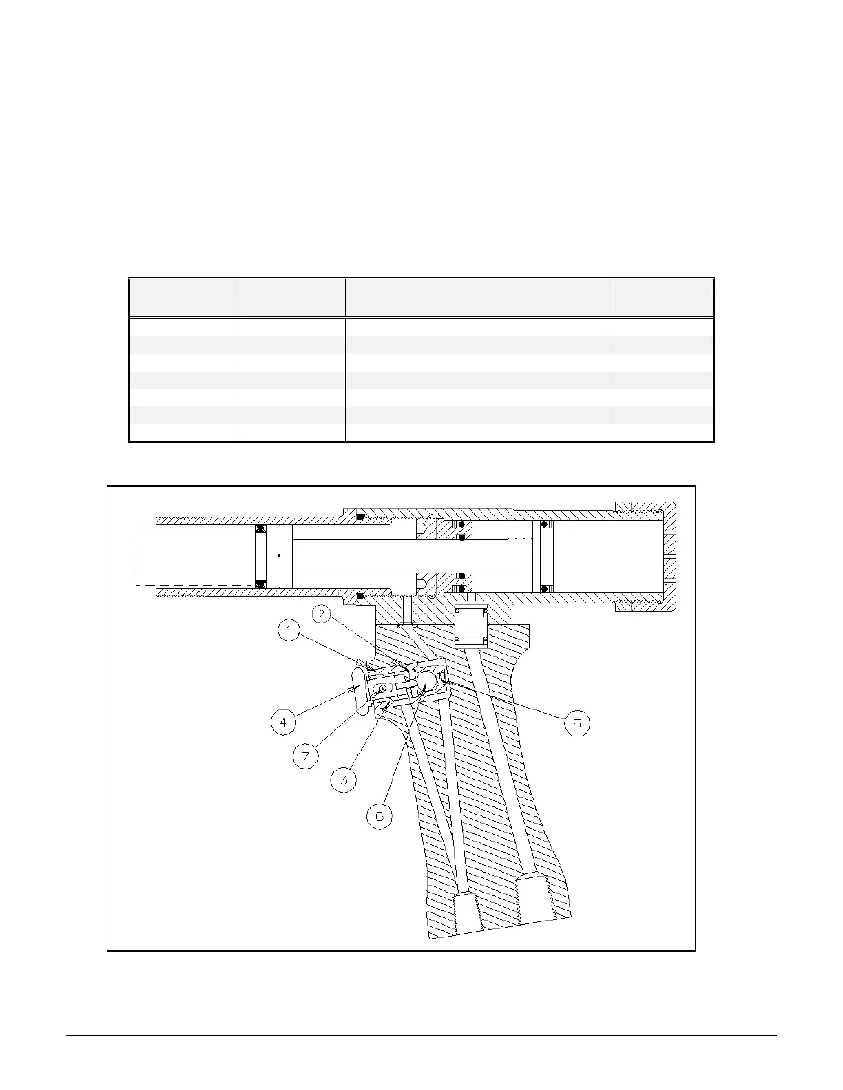
6.3 PREVIOUS LITTLE BRUTE TRIGGER ASSEMBLY; PARTS LIST AND DIAGRAM
All pullers with serial numbers previous to those listed in Table 6.0-1 have the trigger assembly detailed below.
These trigger assemblies can be readily identified by the aluminum pushbutton. (The new trigger assemblies
have a brass pushbutton). These trigger assemblies can be reworked by ordering the Cartridge Trigger
Assembly Kit (FTI-CT-RK) or the Little Brute Rework Kit (LB-CT-RK), and the Puller Trigger Rework Tool
Kit (FTI-CT-RKT) in Section 6.1. A diagram of the Little Brute Puller Unit is shown in Figure 6.3-1, with
parts for the previous trigger assembly corresponding to Table 6.3-1:
Table 6.3-1
Previous Little Brute Trigger Assembly
Quantity Description
Pin, 1/8 x 3/4 Stld. Spring
Figure 6.3-1
Diagram of Previous Little Brute Trigger Assembly