FT500 SFI / FT500LITE SFI
20
Engine settings
Below is a table with known alignment values and configurations for most of the cases:
Crank trigger - pattern Engine/brand
Recommended
index position
Cam sync sensor
60-2 BMW, Fiat, Ford (inj. Marelli), Renault, VW, GM
123º (GM)
90º (others)
Not mandatory
48-2 Not mandatory
36-1 Ford (ECU FIC) 90º Not mandatory
36-2-2-2 Subaru 55º Not mandatory
36-2 Toyota 102º Not mandatory
30-1 Not mandatory
30-2 Not mandatory
24-1 Hayabusa 110º Not mandatory
24-2 Suzuki Srad 1000 Not mandatory
24 (crank) ou 48 (cam) 60º Falling edge
15-2 bikes Honda CB300R Not mandatory
12+1 Honda Civic Si 210º ou 330º Not mandatory
12-1 bikes Honda/Suzuki/Yamaha Not mandatory
12-2 Not mandatory
12 (cranck) ou 24 (cam) Motoscycles/AEM EPM/ distributors Honda 92/95-96/00 Falling edge
8 (cranck) ou 16 (cam) Falling edge
4+1 (vira) Not mandatory
4 (cranck) ou 8 (cam) 8 cylinders 70° Falling edge
3 (cranck) ou 6 (cam) 6 cylinders 60º Falling edge
2 (vira) ou 4 (cam) 4 cylinders 90º Falling edge
WARNING:
Ignition calibration values on this table are just a
start point. ALWAYS perform the ignition calibration
according to chapter 16. When the ignition is not
correctly calibrated, the timing shown on the ECU
screen is different from the one that is being applied
to the engine. This may cause serious damage to the
engine.
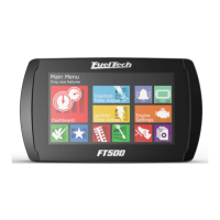
Cam sync sensor
This option indicates if a cam sync sensor will be used and if it uses a
hall effect or magnetic variable reluctance (VR) sensor. This sensor is
mandatory when controlling fuel or timing in sequential mode. Without
cam sync sensor the injection mode will be only semi-sequential or
multipoint. Ignition will be always wasted spark.
Edge
cam sync sensor 4/5
Rising Edge
Falling Edge
Hall/VR with pull-up
Variable Reluctance
Not used
Random - Hall
Random - VR
Random cam sync sensor option is a test mode that automatically
assumes a position for the cam sync signal. Use this only for testing
purposes, as this may cause misfires in some applications. Use this
option only for tests, because with individual coils and sequential
ignition the firing order can be lagged (inverted) in 360º, so the
engine won’t start.
Cam sync sensor edge: this option changes the way the ECU reads
the cam sync signal. As there’s no simple way of telling which one is
the correct option (without an oscilloscope), select the option Falling
edge. If the engine starts with misfires, change this parameter to
Rising edge.
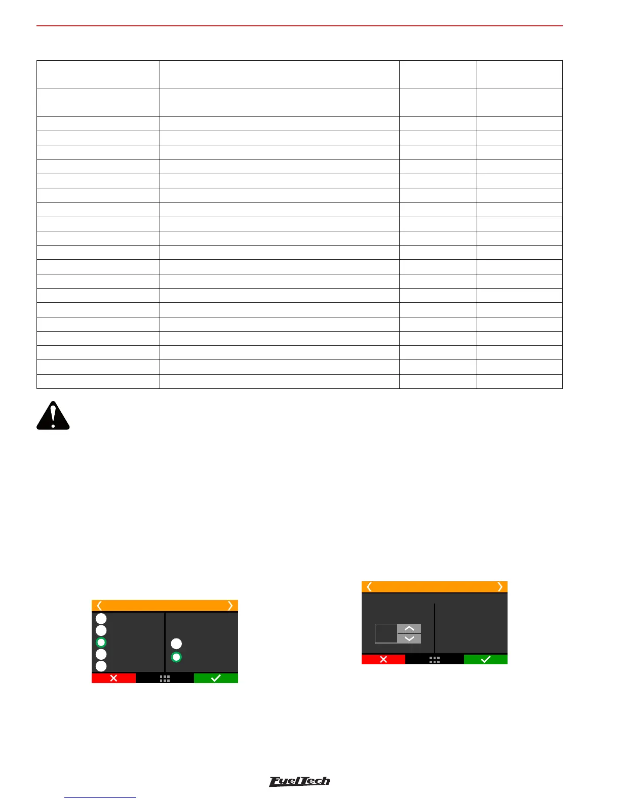
Cam sync position angle
The adjustment is degrees before top dead center (ºBTDC) of cylinder
1 combustion.
Cam Sync Position
RPM signal 5/5
15
°BTDC
Cam Sync
position angle
Engine position angle (BTDC)
when the cam sync sensor is
over the cam sync teeth. This
information is used to improve
noise rejection and prevent
cam sync errors and doesnt
require precise number since it
doesnt affect timing precision.
This angle is not mandatory and won’t affect the ignition calibration.
If you don’t know the position angle, set the same alignment as crank
index position or select the cam sync sensor as random.
With the random mode enabled, the position angle in the log and
diagnostic panel.