FT500 SFI / FT500LITE SFI
90
25. Rotary engines setup
The crank angle sensor (CAS) has two (2) trigger wheels that provide
different signals to the ECU. As shown in picture, the bottom wheel
is a 24 teeth trigger that provides the RPM signal and position of
the eccentric shaft. The top wheel is a 2 teeth trigger that provides
information of the position of the rotor.
FuelTech ECU will control the ignition timing using the reference
of the 24 tooth wheel to spark the leading coil. All ignition timing
programmed in the tables is referenced to the leading coil. Trailing
coil will be fired using the programmed timing split parameter. This
means that if the ignition timing in the main table is 0° and timing split
is 10 °, the ECU will fire the leading coil at 0° and the trailing coil 10°
after leading coil was fired. The timing split parameter is fixed across
all the ignition timing range.
25.1 Crank angle sensor installation and alignment
The Crank Angle Sensor needs to be installed in the engine at 0°
(top dead center position). To align it, follow this quick step by step:
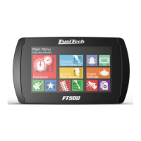
1. Use your ignition timing marks in the damper to align the eccentric
to TDC. The ignition timing mark to be used is shown below.
1
2. Align the Crank Angle Sensor to 0° using the mark in the shaft.
2
3. Install and tighten the Crank Angle Sensor in the engine. After
the steps above are correctly followed, the Crank Angle Sensor
should be aligned at TDC with the eccentric shaft.
25.2 Crank angle sensor wiring
The stock distributor will be read by FT as a Crank Angle Sensor and
Camshaft Position Sensor. Here’s how to connect the FT to your stock
Mazda distributor:
24 Teeth
2 Teeth
Distributor - CAS
2 core
shielded cable
1 core
shielded cable
Shield
From FT
Do not connect the
shielded cable
Function Distributor wire FuelTech wire FuelTech pin
24 teeth signal (crank signal) Red Red from 2 way shielded cable 17
24 teeth sensor negative White White from 2 way shielded cable 8
2 teeth signal (home) Green White from 1 way shielded cable 15
2 teeth sensor negative White/Black Shield from 1 way shielded cable 19
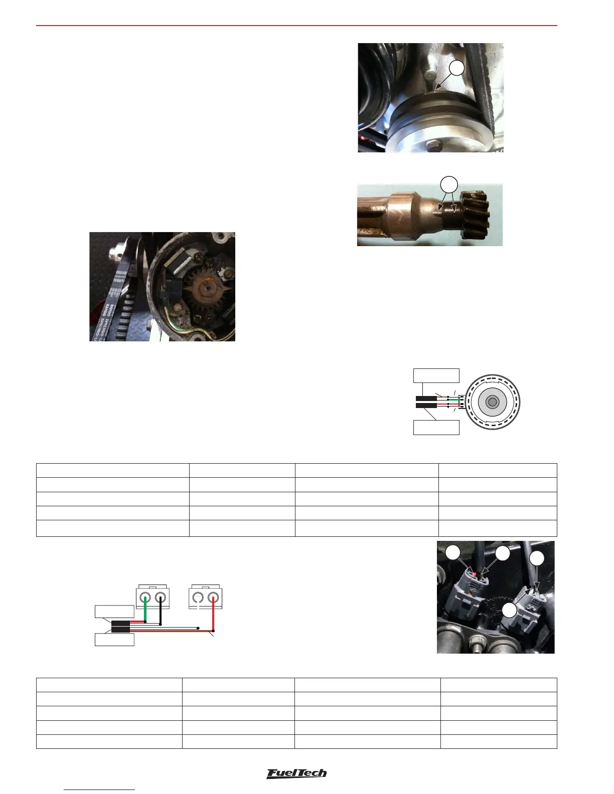
For engines using trigger wheel instead of distributor, here are the
connections:
Function Distributor wire FuelTech wire FuelTech pin
12 teeth sensor (crank signal) Green Red from 2 way shielded cable 17
12 teeth sensor negative Black White from 2 way shielded cable 19
1 tooth sensor signal (home) White white from 1 way shielded cable 15
1 tooth sensor negative Red shield from 1 way shielded cable 19
12 Teeth sensor 1 Teeth sensor
Shield
From FT
2 core
shielded cable
1 core
shielded cable
Do not connect the
shield from the 2 core
1 - SHIELD from shielded cable
2 - WHITE from shielded cable
(Pin17)
3 - SHIELD from 1 way cable
(split the shield between
both sensors)
4 - White from 1 way from ecu
(pin15)
1
2
3
4
Rotary engines setup