FT500 SFI / FT500LITE SFI
33
Ignition
Obs.: Input Magnetic Pickup
not utilized
Positive Battery (Large Red)
ground of head (large black)
Positive Switch 12V
Orange (Positive Coil)
input Points (White)
+
-
Ignition output Gray 1
MSD Legacy Input
Connect a 500 white wireFT
to the pin on the right
Do not connect
pin on the left
• When experiencing problems with the cut through MSD like no
cut at all or RPM limit always 500 RPM above what was setup,
use the other MSD pin.
Ignition with crank trigger
When controlling the ignition in distributorless systems, wasted spark
or individual coils per cylinder are needed. In this case, coils are
triggered by different outputs, according to the number of cylinders.
Ignition outputs (gray wires) are triggered according to the firing order
set up on the ECU
Example: 4 cylinder engine with individual coils:
Gray outputs are selected automatically, according to the number of
cylinders.
Gray wires that will not be used for ignition control can be set up as
injectors outputs (Peak and Hold driver is mandatory) or auxiliary
outputs (relay needed).
Individual coils – electrical connections
On FT500 / FT500LITE, these connections must be done by matching
the output number with the cylinder number:
• Ignition output #1 controls cylinder #1 coil;
• Ignition output #2 controls cylinder #2 coil;
• Ignition output #3 controls cylinder #3 coil.
When working with dumb coils, an external ignition module must be
used (as the FuelTech SparkPRO). In this case, ignition outputs from
FT500 / FT500LITE are connected to the ignition module inputs.
IMPORTANT:
In the “Ignition” menu, select the ignition output
as “Falling dwell”. In case of selecting the wrong
output type, coil will be damaged.
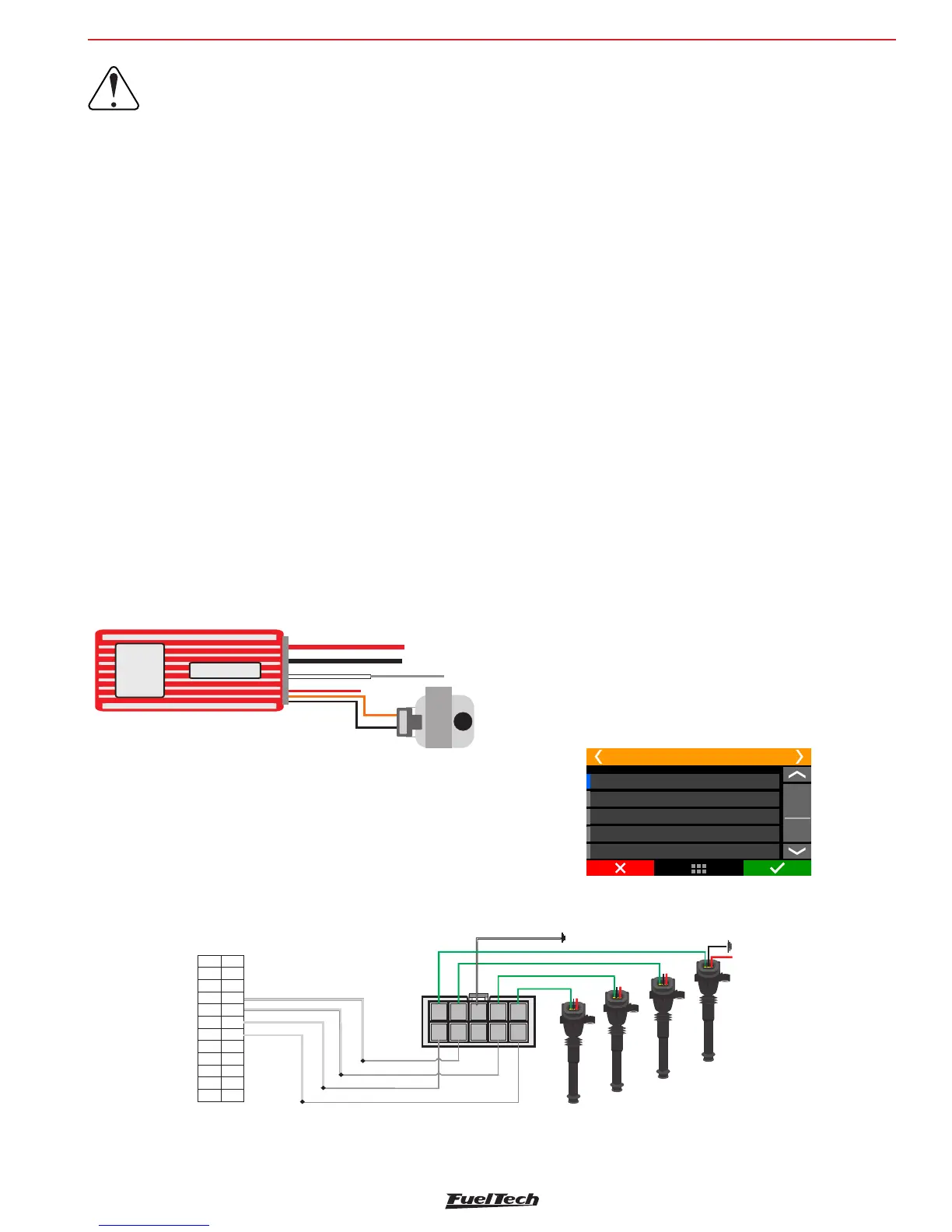
Capacitive discharge ignition module (MSD 6A, MSD 7AL,
Crane, Mallory)
FuelTech’s ignition output must be connected to the MSD ignition
module, (usually, the white wire is the points input). When using a MSD
ignition box, the yellow #1 is automatically set up as ignition output.
The installation of ignition modules must always follow what is indicated
by its manufacturer in the instructions manual. This ignition module
will receive a Points signal from FuelTech. Ignition coil must follow the
ignition module manufacturer recommendations as well.
Important Notes:
• The module must be placed the closest possible to the ignition
coil, and never inside the car, in order to avoid the risk of
interference on electronic devices.
• The length of the wires that connect the ignition module to the
ignition coil must be the shortest possible.
• In “Ignition Setup,” select the output “Rise (CDI)”.
• It is not possible to control the ignition Dwell when using this
type of module.
• To use the ignition cut through MSD, check Chapter 7.3
Grey 2: Ignition - cylinder 2
Grey 4: Ignition - cylinder 4
Grey 3: Ignition - cylinder 3
Wiring harness diagram
Blue 8: Shift Alert
Grey 1: Ignition - cylinder 1
3
4
5
6
78
910
11 12
13
14
15 16
17
18
19 20
21 22
23
24
2
r
222 222
11 111111
3
33333
4
444
Channel 3 input
Channel 1 input
Channel 2 input
Channel 4 input
2
1
2
4
4
4
Switched 12V from relay
Power ground
engine head
Cyl.3
Cyl.1
Cyl.2
Channel 3 output
Channel 1 output
Channel 4 output
Channel 2 output
Power ground - engine head
Spark -4PRO
1
2
34
5
6
78
9
10
• When using MSD ignition modules with a distributor, it is
necessary to connect a FuelTech white wire to the MSD Legacy
input. That makes FT ECU to perform a faster timing control,
especially needed when using Drag Race Features. By default,
white wire #10 is set up automatically as “ignition cut” after the
base map generation, and must be connected to the wire on the
right of the MSD Legacy plug.