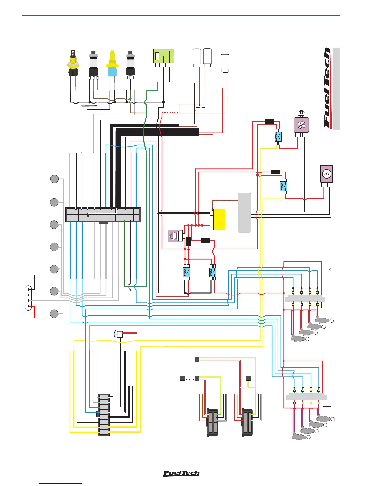
FT500 SFI / FT500LITE SFI
94
Battery negative
A
B
C
PS10-B
PS-10B
Battery negative
B
C
PS10-B
PS-10B
Battery negative
Battery negative
ELECTRIC FUEL PUMP
THERMATIC FAN
+
_
BAT
POWER GROUND
ENGINE
()BLOCK OR CHASSIS
TPS
Battery negative
Signal
5V input
C
A
B
+
-
85
30
86
87
FUEL PUMP RELAY
85
30
86
87
FAN RELAY
15
30
Ignition Switch
1
2
3
4
5
6
7
9
10
11
12
13
14
15
16
17
18
19
20
21
22
23
24
1 * 1 * 1 * 1 * 1 *
2 * * 2 * * 2 * * 2 * * 2 * *
3 * * * 3 * * * 3 * * * 3 * * * 3 * * *
4 * * * * 4 * * * * 4 * * * * 4 * * * * 4 * * * *
5 * * * * * 5 * * * * * 5 * * * * * 5 * * * * * 5 * * * * *
Blue #2
Switched 12V from relay - Red
Cam sync sensor - White
Blue #3
White #11
White #4
White #5
White #6
White #7
Gray #8
Battery negative - Black
24-way Connector
Blue #1
Engine ground (head/block) - Black/White
5V output for sensors - Green/Red
Gray #1
Gray #2
Gray #3
Gray #4
Gray #5
Blue #8
Blue #7
Blue #6
8 * * * * * * * * 8 * * * * * * * * 8 * * * * * * * * 8 * * * * * * * * 8
7 * * * * * * * 7 * * * * * * * 7 * * * * * * * 7 * * * * * * * 7
6 * * * * * * 6 * * * * * * 6 * * * * * * * 6 * * * * * * 6
6 * * * * * * 6 * * * * * * 6 * * * * * * 6 * * * * * * 6
7 * * * * * * * 7 * * * * * * * 7 * * * * * * * 7 * * * * * * * 7
8 * * * * * * * * 8 * * * * * * * * 8 * * * * * * * * 8 * * * * * * * * 8
5 * * * * * 5 * * * * * 5 * * * * * 5 * * * * * 5
4 * * * * 4 * * * * 4 * * * * 4 * * * * 4
11 * * * * * * * * * * * 11 * * * * * * * * * * * 11 * * * * * * * * * * * 11 * * * * * * * * * * * 11
3 * * * 3 * * * 3 * * * 3 * * * 3
2 * * 2 * * 2 * * 2 * * 2
1 * 1 * 1 * 1 * 1 *
8
2 core Shielded cable
1 core Shielded cable
85
30
86
87
EFI RELAY
85
30
86
87
INJECTORS RELAY
PS10-B
PS-150
A
PS10-B
PS-150
OIL PRESSURE
TEMPERATURE
Battery negative
ENGINE
TEMPERATURE
Battery negative
+
_
BAT
POWER GROUND
ENGINE
()BLOCK OR HEAD
TPS
Battery negative
Signal
5V input
15
30
Ignition Switch
1
2
3
4
5
6
7
9
10
11
12
13
14
15
16
17
18
19
20
21
22
23
24
1 * 1 * 1 * 1 * 1 *
2 * * 2 * * 2 * * 2 * * 2 * *
3 * * * 3 * * * 3 * * * 3 * * * 3 * * *
4 * * * * 4 * * * * 4 * * * * 4 * * * * 4 * * * *
5 * * * * * 5 * * * * * 5 * * * * * 5 * * * * * 5 * * * * *
Blue #2
Switched 12V from relay - Red
Cam sync sensor - White
Blue #3
White #11
White #4
White #5
White #6
White #7
Gray #8
Battery negative - Black
Blue #1
Engine ground (head/block) - Black/White
5V output for sensors - Green/Red
Gray #1
Gray #2
Gray #3
Gray #4
Gray #5
Blue #8
Blue #7
Blue #6
8 * * * * * * * * 8 * * * * * * * * 8 * * * * * * * * 8 * * * * * * * * 8
7 * * * * * * * 7 * * * * * * * 7 * * * * * * * 7 * * * * * * * 7
6 * * * * * * 6 * * * * * * 6 * * * * * * * 6 * * * * * * 6
6 * * * * * * 6 * * * * * * 6 * * * * * * 6 * * * * * * 6
7 * * * * * * * 7 * * * * * * * 7 * * * * * * * 7 * * * * * * * 7
8 * * * * * * * * 8 * * * * * * * * 8 * * * * * * * * 8 * * * * * * * * 8
5 * * * * * 5 * * * * * 5 * * * * * 5 * * * * * 5
4 * * * * 4 * * * * 4 * * * * 4 * * * * 4
11 * * * * * * * * * * * 11 * * * * * * * * * * * 11 * * * * * * * * * * * 11 * * * * * * * * * * * 11
3 * * * 3 * * * 3 * * * 3 * * * 3
2 * * 2 * * 2 * * 2 * * 2
1 * 1 * 1 * 1 * 1 *
White
do not use
8
2 core Shielded cable
1 core Shielded cable
85
30
86
87
EFI RELAY
85
30
86
87
INJECTORS RELAY
Shield
Connector
1
2
Gray #6
Gray #7
White #9
Blue #4
Blue #5
Yellow #2
White #3
White #2
Black/White
White #10
White #1
6 * * * * * * 6 * * * * * * 6 * * * * * * 6 * * * * * *
4 * * * * 4 * * * * 4 * * * * 4 * * * * 4 *
* * *
7 * * * * * * * 7 * * * * * * * 7 * * * * * * * 7 * * * * * * *
5 * * * * * 5 * * * * * 5 * * * * * 5 * * * * * 5 * * * * * 5 * * * * *
* * 2 * * 2 * * 2 * *
1 * 1 * 1 * 1 *
3 * * * 3 * * * 3 * * * 3
* * * 3 * * * 3 * * *
* 1 * 1 * 1 * 1 *
3 * * * 3 * * * 3 * * * 3 * * * 3 * * * 3 * * *
2 * * 2 * * 2
* 1 * 1 *
1 * 1 * 1 * 1 * 1 * 1 *
10 ********** 10 ************ 10 ************ 10 **********
9 * * * * * * * * * 9 * * * * * * * * * 9 * * * * * * * * * 9 * *
* * * * * * * 9 * * * * * * * * *
White #8
8 * * * * * * * * 8 * * * * * * * * 8 * * * * * * * * 8 * * * *
* * * * 8 * * * * * * * *
* * * * 4 * * * * 4 * * * * 4 * * * *
4 * * * * 4 * * * * 4 * * * *
Black/White
Yellow #4
Yellow #1
Yellow #3
+
-
2
4
6
8
Harness Connector
Rear View
Chassis Ground
Peak and Hold 4A/1A
4
3
2
1
4
3
2
1
Switched 12V
1
3
5
7
Chassis Ground
Injectors
Trigger Input
Peak and Hold 4A/1A
4
3
2
1
4
3
2
1
Switched 12V
Connect to chassis (engine block or head)
To Transbrake
button
Connect to chassis
(engine block or head)
Hall
12V input
Signal output
Signal output
PH1
PH2
5V input
Signal output
5V input
Signal output
B
C
A
Battery negative
Signal
Hall
B
C
A
Battery negative
12V input
Signal
CAM SYNC
HALL 1 REAR
CAM SYNC
HALL 2 FRONT
Hall
B
C
A
CRANK HALL 1
24x OR 58X
Battery negative
12V input
Signal
RPM signal input - Red
Blue #1
Blue #3
Blue #5
Blue #7
Injectors
Trigger Input
Blue #2
Blue #4
Blue #6
Blue #8
Power Ground - Black/White
Lambda Output - Yellow/Red
Switched 12V - Red
Battery Ground - Black
6
CAN - Pin 4 - White/Red
CAN - Pin 3 - Yellow/Blue
Harness Connector
Rear View
Power Ground - Black/White
Lambda Output - Yellow/Red
Switched 12V - Red
Battery Ground - Black
6
CAN - Pin 4 - White/Red
CAN - Pin 3 - Yellow/Blue
CAN-Female
Terminator
CAN-Female
Connector
CAN-Connector
FT
CAN-Male
Connector
DCBA
Switched 12V
Signal Ground
Power Ground engine
Switched 12V
or Ground
FUSE
FUSE
FUSE
FUSE
Gray #1
Gray #3
Gray #4
Gray #2
Cyl #3
Coil
Cyl #6
Coil
Cyl #8
Coil
Cyl #5
Coil
Cyl #4
Coil
Cyl #7
Coil
Cyl #2
Coil
Gray #1
electrical diagram LSX V8 MSD - Wasted spark
Eletrical diagram