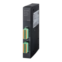
ON: Power supply ON
OFF: Power supply OFF
ON: Safety function running
Flashing: Normal status
ON: Error detected
OFF: Normal status
ON: STO running
OFF: Normal status
Flashing: Parameter being set
3.4 Terminal Function Description
If the restart function setting is enabled (parameter SF18: 1), this is
the terminal that is operated when the safety function status is
operational, and when performing recovery following an
ecf
alarm.
If the restart function is enabled, it will not be possible to restart
unless terminals [RES+] are turned ON→OFF→ON, even if the
status of the safety input terminal is recovered to ON after SS1, or
SLS and SBC activation.
The terminal [RES+] ON and OFF time must be 20 ms or longer.
Electrical specifications
Operating current
when ON
Input circuit : Secured at source
This is the common terminal of [RES+].
If the terminal input turns OFF (open) with a redundant input signal,
the safety function set with parameter SF12 will run.
If either of the input terminals turns OFF (open), an
ecf
alarm will
be output, and the status will be STO. Ensure that the input time
difference between terminals [SIA1+] and [SIA2+] is 50 ms or less.
It is necessary to reboot the power supply to clear the alarm status.
This is the common terminal of [SIA1+].
This is the common terminal of [SIA2+].
If the terminal input turns OFF (open) with a redundant input signal,
the safety function set with parameter SF13 will run.
If either of the input terminals turns OFF (open), an
ecf
alarm will
be output, and the status will be STO. Ensure that the input time
difference between terminals [SIB1+] and [SIB2+] is 50 ms or less.
It is necessary to reboot the power supply to clear the alarm status.
This is the common terminal of [SIB1+].
This is the common terminal of [SIB2+].
This terminal outputs the safety function operating condition.
The operation selection is set with parameter SF20.
Electrical specifications
- Max. load current
when ON
This terminal outputs the safety function operating condition.
The operation selection is set with parameter SF21.
This is the power supply input terminal for SSM signal output.
Electrical specifications: 24 VDC ±10%
This is a redundant output signal. The operation is selected by
setting with parameter SF09, and the terminal turns OFF if the
parameter SF10 speed level is exceeded.
Electrical specifications
- Max. load current
when ON
This is the SSM power supply common terminal.
This is the power supply input terminal for SBC signal output.
Electrical specifications: 24 VDC ±10%
This is the brake signal used to operate the redundant non-excitation
actuating brake. Select SBC function operation with parameter SF11.
The status between terminal [PI_SBC■] and terminal [SBC■] is OFF
(open) when the servomotor is running free with STO. Furthermore,
assign SBC feedback functions (parameters: SF12, SF13) to
terminal [SIA■] or terminal [SIB■], and connect brake operation relay
contact b to the terminal to which the function is assigned.
Electrical specifications
- Max. load current
when ON

 Loading...