2-2
When employing external cooling
t the shipment time, the inverter is set up for mount inside your
equipment or enclosure so that cooling is done all internally.
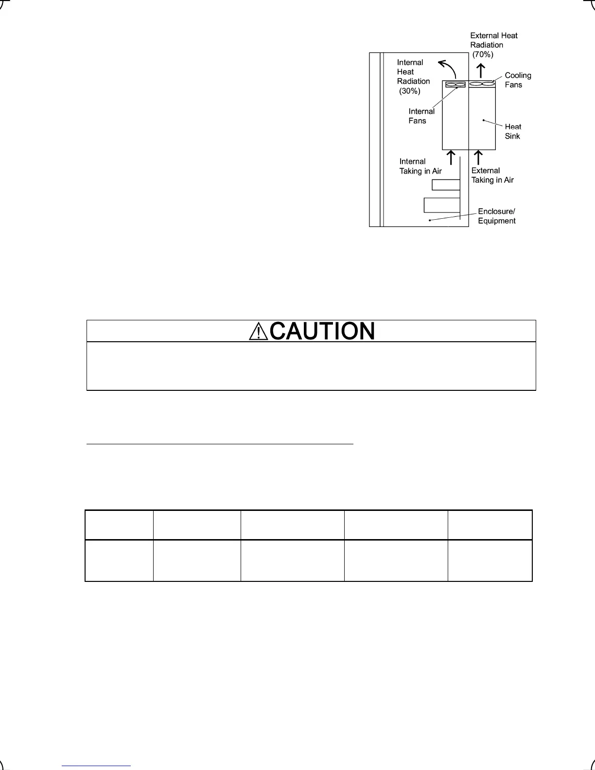
To improve cooling efficiently, you can take the heat sink out of the
equipment or the enclosure (as shown on the right) so that cooling
is done both internally and externally (this is called "external
cooling").
To set up inverters with a capacity of 22 kW or below for "external
cooling," add the optional mounting adapter; to set up ones with a
capacity of 30 kW or above, change the position of the top and
bottom mounting bases as shown below.
For details about the optional mounting adapter, refer to the
Mounting Adapter for External Cooling "PB-F1" Installation
Manual (INR-SI47-0880).
In external cooling, the heat sink, which dissipates about 70% of
the total heat (total loss) generated into air, is situated outside the
equipment or the enclosure. As a result, much less heat is
radiated inside the equipment or the enclosure.
In an environment with high humidity or a lot of fibrous dust,
however, do not use external cooling, which tends to clog the heat
sink.
Figure 2.2 External Cooling
Prevent lint, paper fibers, sawdust, dust, metallic chips, or other foreign materials from getting into the
inverter or from accumulating on the heat sink.
This may result in a fire or accident.
To utilize external cooling for inverters with a capacity of 30 kW
, change the position of the top and bottom
mounting bases from the edge to the center of the inverter as instructed on the next page.
Screws differ in size, length and count for each inverter. Be sure to refer to the table below.
Table 2.3 Screw Count and Tightening Torque
Power supply
voltage
Inverter type
Base fixing screw
(Count)
Case fixing screw
(Count)
Tightening torque
(N
•m)
Three-phase
400 V
FRN30LM1S-4 to
FRN45LM1S-4
M6 × 20
(3 pcs each for upper
and lower sides)
M6 × 12
(3 pcs for upper side)
5.8
Note: A box (
) in the above table replaces C (China), E (EU), A (Asia) or J (Japan) depending on the shipping
destination.

 Loading...


