EasyManua.ls Logo

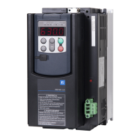
Fuji Electric FRENIC-Lift FRN0015LM2A-4 User Manual

Fuji Electric FRENIC-Lift FRN0015LM2A-4
73 pages
To Next Page IconTo Next Page
Page #1 background imageLoading...
Page #1 background image
Instruction Manual
LM2A series
Three-phase 400 V FRN0006LM2A-4 to FRN0091LM2A-4
Single-phase 200 V FRN0011LM2A-7/FRN0018LM2A-7
Thank you for purchasing our FRENIC-Lift LM2A series of inverters.
This product is designed to drive three-phase induction motors and three-phase permanent magnet
synchronous motors. Read through this manual to become familiar with the handling procedure and
correct use.
Improper handling might result in incorrect operation, short life cycle, or failure of this product as well as
the motor.
Deliver this manual to the end user of this product. Keep this manual in a safe place until this product is
discarded.
For instructions on how to use an optional device, refer to the instruction and installation manuals for that
optional device.
Fuji Electric Co., Ltd. INR-SI47-1894d-E

Table of Contents

Question and Answer IconNeed help?

Do you have a question about the Fuji Electric FRENIC-Lift FRN0015LM2A-4 and is the answer not in the manual?

Fuji Electric FRENIC-Lift FRN0015LM2A-4 Specifications

General IconGeneral
ModelFRN0015LM2A-4
TypeInverter
Rated Power (kW)1.5
Power Rating1.5 kW
Frequency Range0.1 to 120 Hz
Control MethodV/f control, vector control
Protection ClassIP20
Cooling MethodForced air cooling
Output Frequency Range (Hz)0.1-400 Hz
ProtectionOvervoltage, Undervoltage, Short circuit
Weight3.5 kg

Summary

FRENIC-Lift Inverter Preface

Inverter Safety Precautions

General safety warnings and precautions for inverter operation.

Inverter Installation Guidelines

Mounting and Clearance Requirements

Guidelines for installing the inverter on a suitable base and maintaining clearances.

Inverter Wiring Safety Precautions

Safety warnings and procedures for wiring the inverter.

FRENIC-Lift Inverter Operation

General Operation Safety Warnings

Safety precautions during operation, including cover, wet hands, and auto-reset.

Inverter Operation Safeguards

Function Code and Speed Setting Safety

Warnings about function code configuration and speed setting for safety.

Inverter Maintenance and Replacement

Maintenance & Inspection Safety

Safety warnings for maintenance, inspection, and part replacement.

Chapter 1: Before Use

Warning Labels and Safety Notes

Safety warnings and precautions indicated on warning plates.

Inverter Model Identification

Inverter Usage Precautions

General precautions for handling and using inverters.

Usage and Storage Environment

Chapter 2: Mounting and Wiring

Inverter Installation and Mounting Base

Guidelines for mounting the inverter on a base and maintaining clearances.

Main Circuit Terminals: Functions and Wiring

Table detailing functions and wiring order for main circuit terminals.

Control Terminals: Analog/Digital Input Functions

Details on analog and digital input control circuit terminals and their functions.

Connection Diagrams with Enable Input

Illustrative diagrams for connecting the inverter with the Enable input function.

Connection Diagrams for Larger Models

Connection diagrams for FRN0039LM2A-4 to FRN0091LM2A-4 models.

Control PCB Slide Switch Settings

Instructions for setting slide switches on the control PCB for operation customization.

Chapter 3: Keypad Operation

Chapter 4: Motor Test Run

Pre-Power ON Safety Checks

Essential checks before powering on the inverter for the first time.

Function Code Configuration for Test Run

Guidance on setting function codes based on motor and machinery design values.

Motor Test Run Procedure

Step-by-step instructions for test running the motor using the keypad.

Power ON and Initial Verification

Procedure for powering on the inverter and verifying initial status.

Chapter 5: Troubleshooting

Alarm Codes Quick List

A summary of alarm codes and their descriptions for quick reference.

Additional Alarm Codes and Errors

Further alarm codes related to communication, speed, torque, and logic errors.

Chapter 6: Maintenance and Inspection

Daily Inspection Procedures

Routine visual checks for operation errors, environment, and physical condition.

Conductor and Terminal Block Inspection

Visual inspection of conductors, wires, and terminal blocks for damage or defects.

Main & Control Circuit Periodic Inspection

Inspection of DC link capacitor, transformers, contactors, PCBs, and cooling fans.

Periodic Inspection Procedures

Detailed checks for environment, input voltage, keypad, and structure.

Chapter 7: Specifications

Chapter 8: Standards Compliance

Functional Safety Standard Compliance

Overview of functional safety standard compliance, focusing on Safe Torque Off (STO).

Related product manuals