EasyManua.ls Logo

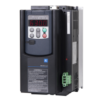
Fuji Electric FRENIC-Lift FRN0025LM2A-4 User Manual

Fuji Electric FRENIC-Lift FRN0025LM2A-4
73 pages
To Next Page IconTo Next Page
Page #1 background imageLoading...
Page #1 background image
Instruction Manual
LM2A series
Three-phase 400 V FRN0006LM2A-4 to FRN0091LM2A-4
Single-phase 200 V FRN0011LM2A-7/FRN0018LM2A-7
Thank you for purchasing our FRENIC-Lift LM2A series of inverters.
This product is designed to drive three-phase induction motors and three-phase permanent magnet
synchronous motors. Read through this manual to become familiar with the handling procedure and
correct use.
Improper handling might result in incorrect operation, short life cycle, or failure of this product as well as
the motor.
Deliver this manual to the end user of this product. Keep this manual in a safe place until this product is
discarded.
For instructions on how to use an optional device, refer to the instruction and installation manuals for that
optional device.
Fuji Electric Co., Ltd. INR-SI47-1894d-E

Table of Contents

Question and Answer IconNeed help?

Do you have a question about the Fuji Electric FRENIC-Lift FRN0025LM2A-4 and is the answer not in the manual?

Fuji Electric FRENIC-Lift FRN0025LM2A-4 Specifications

General IconGeneral
TypeInverter
ModelFRN0025LM2A-4
Rated Output Current5.5 A
Cooling MethodForced air cooling
Current5.5A
SeriesFRENIC-Lift
Enclosure RatingIP20
Input Voltage3-phase, 380-480V AC
Control MethodV/F control
Voltage380-480V
Protection FeaturesOvervoltage, undervoltage, overheat
Operating Temperature-10 to 50°C
Storage Temperature-20 to +60°C
HumidityUp to 95% (non-condensing)
Altitude1000 m above sea level

Summary

Product Overview and Safety Warnings

Important Safety CAUTION

Critical warnings regarding handling, operation, and potential hazards.

Preface and Usage Guidance

Safety Precautions and Application

Classification of safety warnings and intended application of the inverter.

Installation and Wiring Safety

Installation Safety

Safety measures for installing the inverter to prevent fire or accidents.

Wiring Safety Precautions

Safety guidelines for connecting wires to prevent electric shock or fire.

Wiring and Operation Safety

Wiring Safety Warnings

Additional wiring safety instructions to prevent fire or electric shock.

Operation Safety Warnings

Safety precautions during inverter operation to avoid accidents.

Operation Hazards and Handling

Operation Hazards

Potential risks and consequences of incorrect operation.

Maintenance, Disposal, and Document Aids

Maintenance and Inspection

Guidelines for daily and periodic inspection of the inverter.

Canadian/US Wiring and Protection

Chapter 2: Installation and Wiring

Inverter Installation

Procedures and requirements for mounting the inverter.

Connection Diagrams

Connection Diagram with Enable Input

Wiring diagram illustrating the use of the Enable input function.

Chapter 3: Operation Using the Keypad

Keypad Operation Overview

Introduction to operating the inverter via the optional keypad.

Chapter 4: Motor Test Run

Pre-Power On Checks

Essential checks before powering the inverter on.

Function Code Configuration

Configuring Function Codes for Test Run

Guide to setting motor parameters and function codes.

Motor Operation Checks and Preparation

Inverter Test Run Procedure

Step-by-step guide for testing motor operation.

Chapter 5: Troubleshooting

Alarm Codes Overview

List and descriptions of alarm codes indicating inverter faults.

Chapter 6: Maintenance and Inspection

Daily Inspection

Routine checks to ensure proper inverter operation.

Periodic Inspection Guide

Scheduled inspections for long-term reliability.

Periodic Maintenance

Periodic Inspection Details

Detailed check items for periodic inspections.

Chapter 7: Specifications

Standard Model: Three-phase 400V Series

Technical specifications for the 400V series inverters.

Specifications: Single-phase 200V Series

Single-phase 200V Series

Technical specifications for the 200V series inverters.

EMC Standards and Installation

Recommended EMC Installation Procedure

Procedures to ensure system compliance with EMC Directive.

Functional Safety Standard Compliance

Functional Safety Performance

Performance data for safety functions like STO.

Functional Safety Standard Notes

Wiring for Safety Inputs

Critical notes for wiring safety-related input terminals.

Functional Safety Testing

Related product manuals