2-4
(3) Mounting direction
Horizontal layout is recommended when two or more inverters are to be installed in an equipment or enclosure.
As long as the ambient temperature is 40°C or lower, inverters may be mounted side-by-side without any gap
between them. If it is necessary to mount the inverters vertically, install a partition plate or the like between the
inverters so that any heat radiating from an inverter will not affect the one/s above.
Do not mount the inverter upside down or horizontally. Doing so will reduce the heat dissipation
efficiency of the inverter and cause the overheat protection function to operate, so the inverter will not
run.
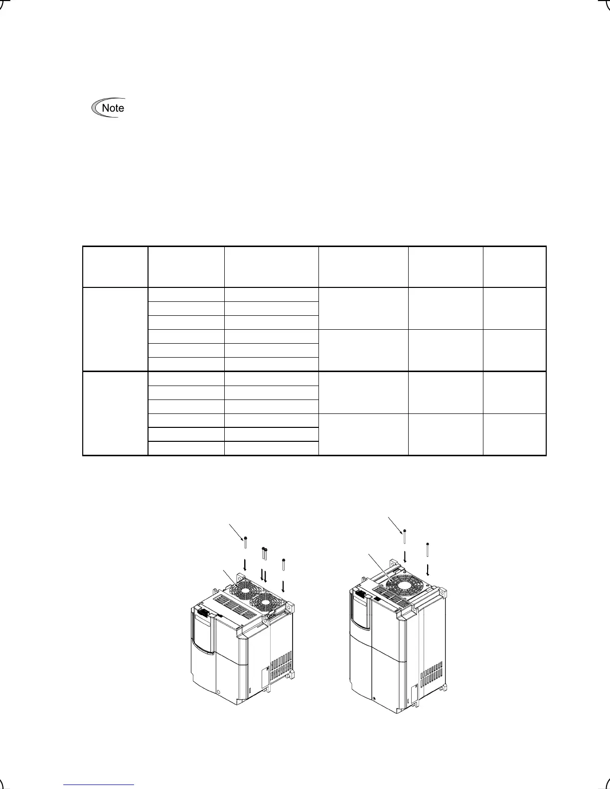
(4) Solving abnormal vibration after installation
If any vibration in the surroundings reaches the inverter and causes abnormal vibration to the cooling fan(s) or
the keypad, fix them firmly using the fixing screws provided as accessories.
Fixing the cooling fan(s)
Table 2.4 Fixing Screws
Power
supply
voltage
Applicable
motor rating
(kW)
Inverter type
Screw size
(accessory)
Tightening
torque
(N·m)
Refer to:
Three-
phase
200 V
5.5 FRN5.5LM1S-2
M4x35 (4 pcs) 0.8 Figure A
7.5 FRN7.5LM1S-2
11 FRN11LM1S-2
15 FRN15LM1S-2
M4x50 (2 pcs) 0.8 Figure B
18.5 FRN18.5LM1S-2
22 FRN22LM1S-2
Three-
phase
400 V
5.5 FRN5.5LM1S-4
M4x35 (4 pcs) 0.8 Figure A
7.5 FRN7.5LM1S-4
11 FRN11LM1S-4
15 FRN15LM1S-4
M4x50 (2 pcs) 0.8 Figure B
18.5 FRN18.5LM1S-4
22 FRN22LM1S-4
Note: A box (
) in the above table replaces C (China), E (EU), A (Asia) or J (Japan) depending on the shipping
destination.
Figure A Figure B
Figure 2.4 Fixing the Cooling Fan(s)
ttached screws
Cooling fans
ttached screws
Cooling fan

 Loading...


