2-7
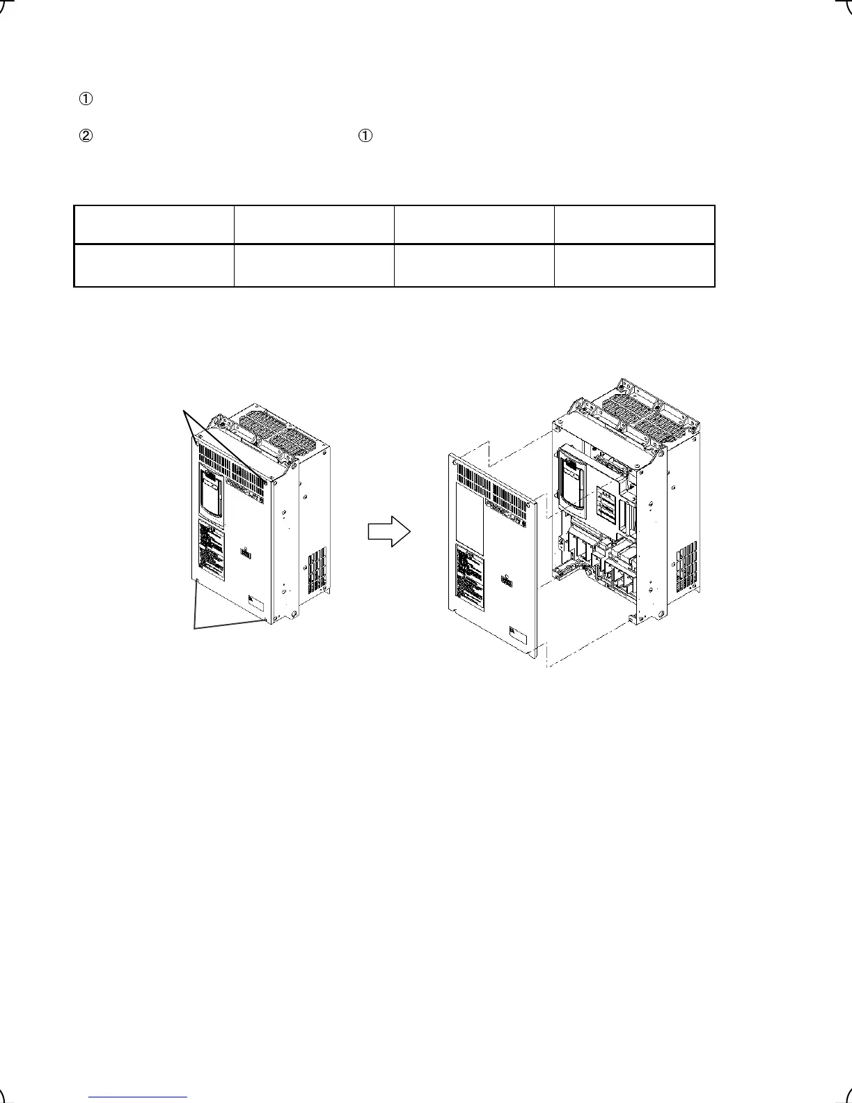
(3) For inverters with a capacity of 30 kW or above
Removing and mounting the cover
To remove the front cover, loosen the four fastening screws, hold it with both hands, and slide it upward.
(Refer to Figure 2.7.)
Put the front cover back in reverse order of . Make sure to properly match the position of the screw holes
on both of the front cover and inverter case.
Table 2.5 Screw Count and Tightening Torque
Power supply voltage Inverter type Front cover screw
Tightening torque
(N·m)
Three-phase 400 V
FRN30LM1S-4 to
FRN45LM1S-4
M4 x 8 (4 pcs) 1.8
Note: A box (
) in the above table replaces C (China), E (EU), A (Asia) or J (Japan) depending on the shipping
destination.
Figure 2.8 Removing and Mounting the Cover (FRN30LM1S-4)
Fastening screws
Fastening screws
Front cover

 Loading...


