Do you have a question about the Fuji Electric FRN0001C2S-2A FRN0002C2S-2A FRN0004C2S-2A FRN0006C2S-2A FRN0010C2S-2A FRN0012C2S-2A FRN0020C2S-2A FRN0025C2S-2A FRN0033C2S-2A FR and is the answer not in the manual?
| Models | FRN0001C2S-2A, FRN0002C2S-2A, FRN0004C2S-2A, FRN0006C2S-2A, FRN0010C2S-2A, FRN0012C2S-2A, FRN0020C2S-2A, FRN0025C2S-2A, FRN0033C2S-2A |
|---|---|
| Frequency | 50/60 Hz |
| Humidity | 95% RH or less (non-condensing) |
| Enclosure Rating | IP20 |
| Input Voltage | 200-240V AC |
| Output Capacity Range | 0.4 to 3.7 kW |
| Output Frequency Range | 400 Hz |
| Output Voltage | 3-Phase 200-240VAC |
| Cooling Method | Forced air cooling |
| Protection Features | Overcurrent, Overvoltage, Undervoltage, Overload, Short circuit, Ground fault, Overheat |
| Operating Temperature | -10°C to +50°C |
| Storage Temperature | -20°C to +60°C |
| Altitude | 1000 m (3300 ft) above sea level or less |
Verifying package contents and checking for any damage or missing parts upon delivery.
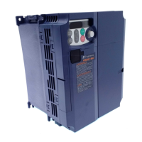
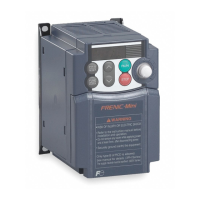
Illustrates the physical layout and key components of the inverter.
Guidelines for safely carrying and transporting the inverter to prevent damage.
Specifies environmental conditions required for proper temporary and long-term storage.
Details the environmental conditions required for optimal inverter performance and longevity.
Provides instructions and safety precautions for physically mounting the inverter.
Step-by-step guide and precautions for connecting power and control wiring to the inverter.
Identifies and explains the function of each button and display element on the inverter's keypad.
Describes the three main operational modes: Running, Programming, and Alarm.
Details how to operate the inverter in running mode, including monitoring status and controlling the motor.
Explains how to navigate menus and set function codes for configuring inverter parameters.
Describes how the inverter enters alarm mode and how to view and manage alarms.
Step-by-step procedure for performing an initial test run of the motor with the inverter.
Guidelines for operational procedures after confirming successful test runs.
Provides comprehensive tables listing all available function codes and their parameters.
Detailed explanations of individual function codes and their usage for configuring inverter behavior.
Specific considerations and notes for operating Permanent Magnet Synchronous Motors (PMSM).
Initial steps and safety precautions to take before attempting to troubleshoot the inverter.
Troubleshooting steps for issues where the LED monitor shows no specific alarm code.
Guidance on interpreting alarm codes and resolving issues indicated by the LED monitor.
Troubleshooting steps for unexpected patterns on the LED monitor without an explicit alarm code.
Routine visual checks to perform on the inverter during normal operation.
Detailed procedures for periodic inspections to ensure long-term reliability and performance.
Identifies components recommended for periodic replacement based on estimated service life.
Procedures for measuring electrical parameters in the main circuit for diagnostic purposes.
Guidelines for performing insulation tests on the main and control circuits.
Information on how to make inquiries and details about the product warranty.
Technical specifications for standard inverter models, including ratings and dimensions.
Technical specifications for semi-standard models featuring built-in EMC filters.
Lists common specifications applicable across various inverter models.
Details the functions and specifications of the inverter's terminals.
Provides dimensional drawings and measurements for standard inverter models.
Explains the function and application of MCCBs for power circuit protection.
Details the function and application of RCDs/ELCBs for overload and short-circuit protection.
Describes the function and application of magnetic contactors for switching power sources.
Describes the use of external potentiometers for setting drive frequency.
Explains the functionality of the remote keypad for operation and configuration.
Details the extension cables for remote keypad and USB-RS-485 converter connections.
Describes the USB-RS-485 converter for PC communication.
Introduces Windows-based software for configuring function code data.
Explains the role of surge absorbers in protecting power systems from surges and noise.
Describes surge killers for eliminating surge currents and preventing damage from surges.
Explains the function of arresters in suppressing surge currents and noise.
Describes the frequency meter for displaying frequency based on inverter output signals.
Information on compliance with North American safety standards (UL and CSA).
Details compliance with European Directives (EMC and Low Voltage).
Explains compliance requirements related to Electromagnetic Compatibility (EMC) standards.
Provides guidance for installing the inverter to ensure full compliance with EMC Directive.