x
Conformity to UL standards and Canadian standards (cUL certification) (Continued)
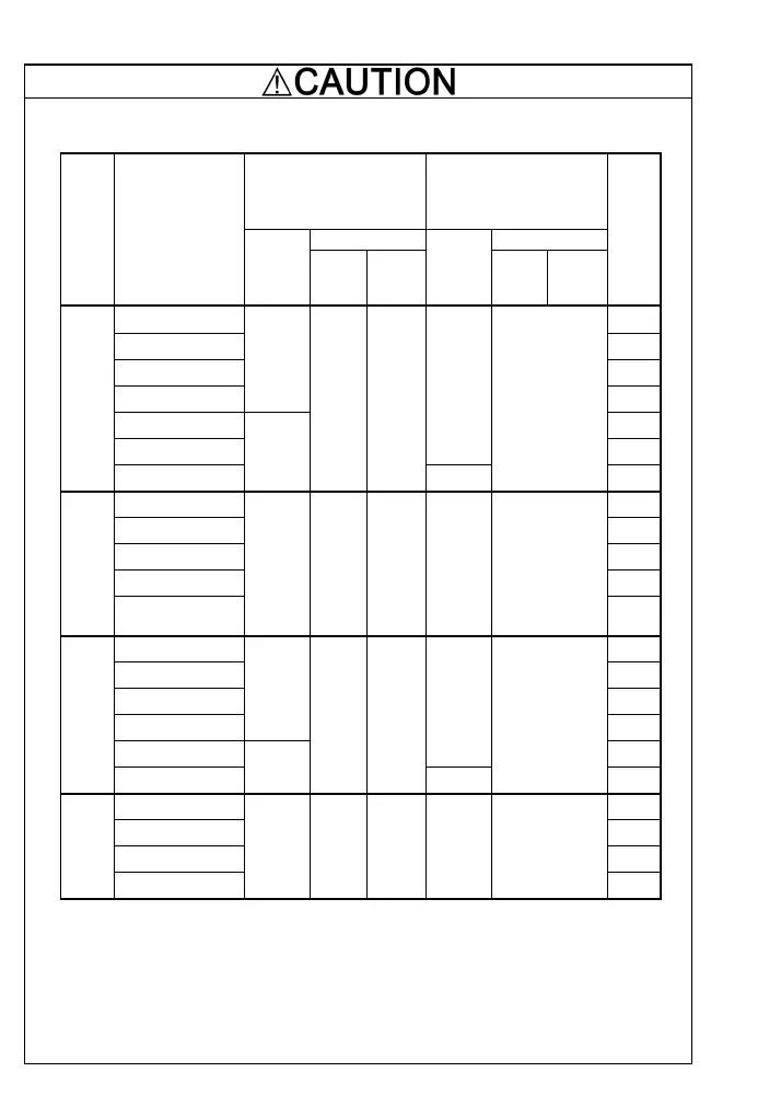
6. Install UL certified fuses between the power supply and the inverter, referring to the table
below.
Notes 1) A box (
) in the above table replaces S or E depending on the enclosure.
2) A box (
) in the above table replaces A, C, E, or J depending on the shipping destination.
3) Asterisks (**) in the above table denote the following:
21: Braking resistor built-in type; None: Standard
*1: Denotes the relay contact terminals for 30A, 30B and 30C.
*2: Denotes control terminals except for 30A, 30B and 30C.
Required torque
Ib-in (N·m)
Wire size
AWG or kcmil (mm
2
)
Control circuit Control circuit
Power
supply
voltage
Inverter type
Main
terminal
*1
TERM1
*2
TERM2-1
TERM2-2
Main
terminal
*1
TERM1
*2
TERM2-1
TERM2-2
Class J fuse
current (A)
FRN0.1C1
-2 3
FRN0.2C1
-2 6
FRN0.4C1
-2 10
FRN0.75C1
-2
10.6
(1.2)
15
FRN1.5C1
-2** 20
FRN2.2C1
-2**
14
30
Three-phase
200V
FRN3.7C1
-2**
15.9
(1.8)
3.5
(0.4)
1.8
(0.2)
10
20
(0.5)
40
FRN0.4C1
-4 3
FRN0.75C1
-4 6
FRN1.5C1
-4** 10
FRN2.2C1
-4** 15
Three-phase
400V
FRN3.7C1
-4**
-
**
15.9
(1.8)
3.5
(0.4)
1.8
(0.2)
14
20
(0.5)
20
FRN0.1C1
-7 6
FRN0.2C1
-7 6
FRN0.4C1
-7 10
FRN0.75C1
-7
10.6
(1.2)
15
FRN1.5C1
-7
14
30
Single-phase
200V
FRN2.2C1
-7
15.9
(1.8)
3.5
(0.4)
1.8
(0.2)
10
20
(0.5)
40
FRN0.1C1
-6 6
FRN0.2C1
-6 10
FRN0.4C1
-6 15
Single-phase
100V
FRN0.75C1
-6
10.6
(1.2)
3.5
(0.4)
1.8
(0.2)
14
20
(0.5)
30
 Loading...