Do you have a question about the FujiFilm FinePix A310 EG and is the answer not in the manual?
Detailed technical specifications for the FinePix A310 camera model.
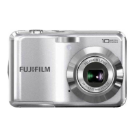
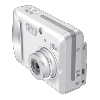
Identifies and labels all external parts of the camera for user reference.
Lists and illustrates the main internal components of the camera for disassembly.
Step-by-step instructions for safely removing the rear panel assembly.
Detailed procedure for detaching the LCD unit from the camera.
Instructions for safely disconnecting and removing the main Printed Wiring Board.
Guide for disassembling the battery compartment cover and holder.
Procedure for safely removing the camera's lens unit.
Steps for detaching the internal cabinet structure.
Instructions for removing the switch Printed Wiring Board.
Procedure for disassembling the link assembly.
Guide for removing the CCD Printed Wiring Board assembly.
Important safety and handling notes related to circuit diagrams and component replacement.
Table listing major internal blocks and their primary functions within the camera.
In-depth explanation of how key camera blocks and their integrated circuits operate.
A high-level visual representation of how different camera modules connect and interact.
Detailed diagram showing all major connection points and interfaces between camera blocks.
Detailed schematic for the camera's CCD sensor and related circuitry.
Schematic diagram illustrating the power switch and associated circuitry.
Schematic detailing the core camera functions and processing blocks.
Schematic for the image processing and system control circuitry.
Detailed schematic of the camera's power generation and distribution system.
Schematic illustrating the video output and related signal processing.
Schematic focusing on the primary integrated circuits controlling camera functions.
Schematic detailing the operation and connections of user interface switches.
Schematic for the rear panel switch mechanisms.
Schematic for the motor control circuits (AF, zoom, iris).
Schematic outlining the connections and drive signals for the LCD screen.
Detailed schematic for the camera's flash charging and firing circuitry.
Layout diagrams showing the placement of components on the main PWB.
Layout diagrams showing component placement on the sub PWB.
Specifies the sequence for performing adjustments after replacing key components.
Lists the essential measuring instruments needed for camera adjustments.
Lists required jigs, cables, and software for performing camera adjustments.
Illustrates how to connect the camera, PC, and adjustment jigs.
Details the necessary setup of lighting and patterns for camera adjustments.
Step-by-step guide for installing the necessary software drivers on a PC.
Instructions for installing and launching the camera adjustment software.
Procedure for initializing the adjustment software before use.
Guide on how to launch and navigate the camera adjustment software interface.
Instructions for inputting CCD data, crucial after replacing the lens or main PWB.
Detailed steps for performing various camera adjustments like shutter and white balance.
Procedure for adjusting the camera's autofocus system, including backlash and reset.
Steps for calibrating the camera's flash unit for optimal performance.
Procedure for adjusting the video output signal quality.
Steps to measure and adjust the camera's battery voltage settings.
Instructions for updating or re-flashing the camera's firmware.
Crucial final step involving destination, USB ID, and product mode settings.
Lists necessary measuring tools for performing camera inspections.
Diagrams showing how to connect test equipment to the camera.
Detailed checks and settings to verify camera functionality and factory defaults.
Lists all items included in the camera's packaging for various regional models.
Detailed parts breakdown for the front section of the camera cabinet.
Component list for the main Printed Wiring Board assembly.
Detailed parts breakdown for the rear section of the camera cabinet.
Comprehensive list of electrical parts, switches, connectors, and fuses used in the camera.
A log for recording issued technical updates and service bulletins for the device.
| Image Sensor | CCD |
|---|---|
| Optical Sensor Size | 1/2.7" |
| Optical Zoom | 3x |
| Focus Adjustment | Automatic |
| Max Shutter Speed | 1/2000 sec |
| Min Shutter Speed | 2 sec |
| Viewfinder Type | Optical |
| LCD Screen Size | 1.5" |
| Screen Type | LCD |
| Optical Sensor Resolution | 3.2 MP |
| Light Sensitivity | ISO 100, ISO 200, ISO 400 |
| Exposure Modes | Automatic, program |
| Shooting Programs | Landscape, Sports, Night scene, Portrait |
| White Balance | Automatic |
| White Balance Presets | Daylight, Fluorescent, Tungsten |
| Exposure Compensation | ±2 EV range, in 1/3 EV steps |
| Metering Modes | Multi-segment |
| Flash Modes | Auto, Red-eye reduction |
| Effective Flash Range | 0.3 m - 3.5 m |
| Battery Type | 2 x AA |