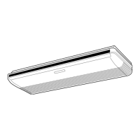
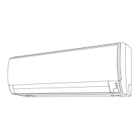
Fig. 1 Indoor Unit
1
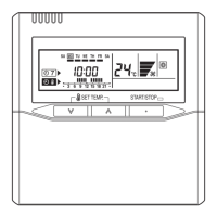
Operating Control Panel (Fig. 2)
2
MANUAL AUTO button
●
When the MANUAL AUTO button is
pressed in for more than 10 seconds, the
forced cooling operation will start.
●
The forced cooling operation is used at
the time of installation.
Only for authorized service personnel's
use.
●
When the forced cooling operation starts
by any chance, press the START/STOP
button to stop the operation.
●
Please press the button at
FILTER IN-
DICATOR RESET
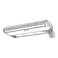
3
Indicator (Fig. 3)
4
Remote Control Signal Receiver
5
OPERATION Indicator Lamp (green)
6
TIMER Indicator Lamp (orange)
●
If the TIMER indicator lamp fl ashes when
the timer is operating, it indicates that a
fault has occurred with the timer setting
(See Page 17 Auto Restart).
7
ECONOMY Indicator Lamp (green)
●
ECONOMY indicator lamp lights when
ECONOMY OPERATION and MINIMUM
HEAT OPERATION is operating.
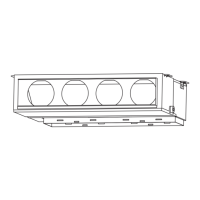
8
Intake Grille (Fig. 4)
9
Front Panel
0
Air Filter
A
Airfl ow Direction Louver
B
Right-Left Louver
(behind Airfl ow Direction Louver)
C
Drain Hose
Fig. 5 Remote Controller
D
Signal Transmitter
E
MODE button
F
10˚C HEAT button
G
ECONOMY button
H
SLEEP button
I
TIMER MODE button
J
FAN button
K
START/STOP button
L
SET button (Vertical)
M
SWING button
N
SET TEMP. button (
/ )
O
TIMER SET ( / ) button
P
CLOCK ADJUST button
Q
TEST RUN button
●
This button is used when installing the air
conditioner, and should not be used un-
der normal conditions, as it will cause the
indoor unit’s thermostat function to oper-
ate incorrectly.
●
If this button is pressed during normal op-
eration, the indoor unit will switch to test
operation mode, and the Indoor Unit’s
OPERATION Indicator Lamp and TIMER
Indicator Lamp will begin to fl ash simulta-
neously.
●
To stop the test operation mode, press
the START/STOP button to stop the air
conditioner.
R
RESET button
S
Remote Controller Display(Fig.6)
T
Temperature SET Display
U
Operation Mode Display
V
SLEEP TIMER Display
W
Transmit Indicator
X
Fan Speed Display
Y
SWING Display
Z
Timer Mode Display
[
Clock Display
En-4
9332280029-04_OM.indb Sec1:49332280029-04_OM.indb Sec1:4 2/25/2013 3:27:49 PM2/25/2013 3:27:49 PM