01-39
1-30-4 ERROR CHECK MODE
•
In this mode, abnormality that is occurring now can be confirmed.
Confirm Chapter 2 " TROUBLE SHOOTING" in detail.
(Table : 22 Procedure for Error Check Mode )
(Table : 23 Demand Response Mode )
Procedure Operation
Power
Mode
1
2
3
Check that the "ERROR" LED blinking (Hi-speed),
and then short press the ENTER SWITCH 1 time.
When the MODE SWITCH is pressed for more than
3 seconds, the Error history is cleared.
Error code is displayed by lighting LED.
(Refer to Table : 21)
: Light ON: Light OFF 2 : 2 Times Blinking
n : n Times Blinking
Error L1 L2 L3 L7L6L5L4
2
2 2 2 2 2 2 2 2 2
n n
Blinking
Hi-speed
1-31. DEMAND RESPONSE OPERATION (For Aust model)
•
•
•
•
This product is designed to be compatible with Air Conditioning Demand Response program.
To utilize the function, Demand Response (DR) adapter kit that interconnects your air conditioner and
Demand Response Enabling Device (DRED) needs to be installed in your air conditioning system,
and you need a separate arrangement.
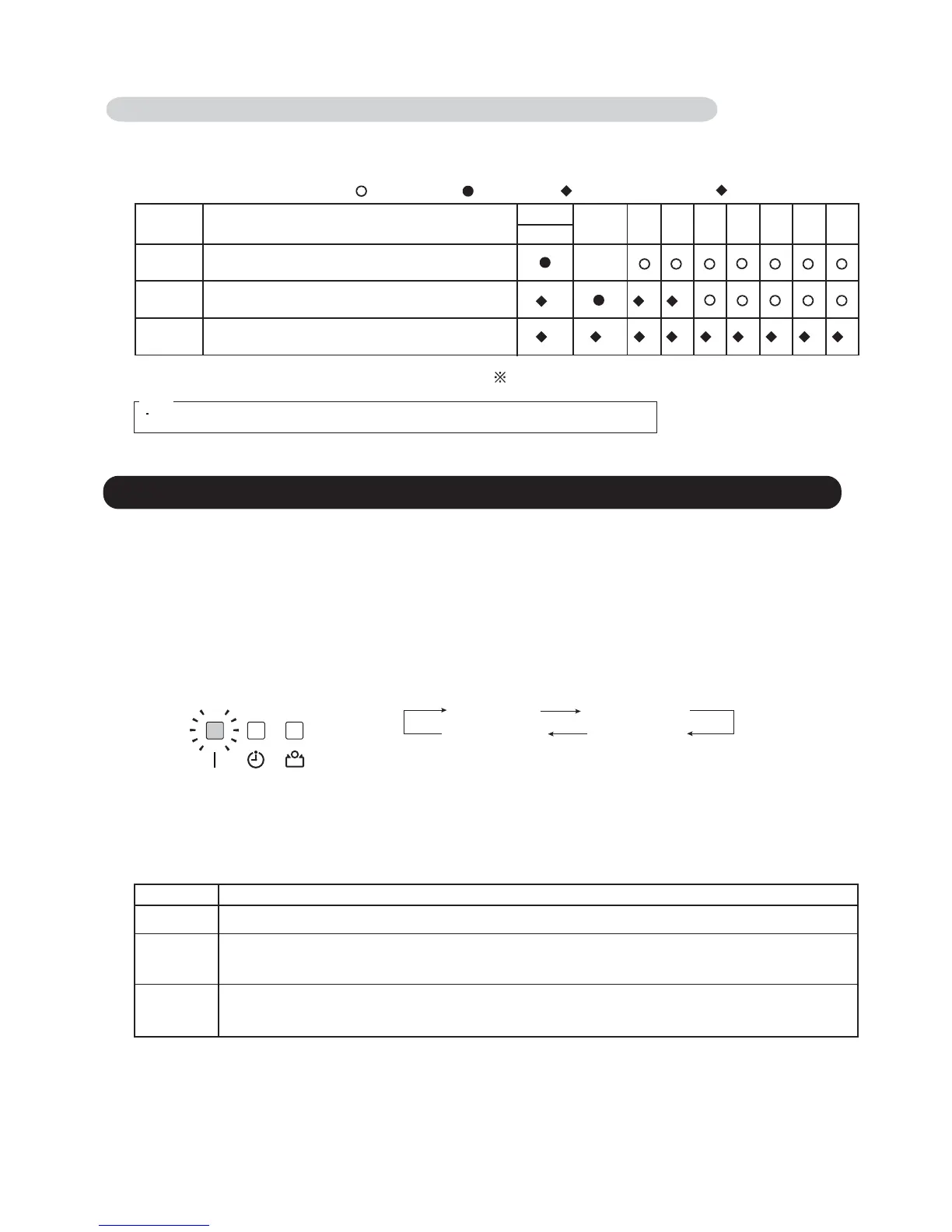
When your electricity supplier activates one of the following 3 DR modes, the air conditioner switches over to
the appropriate operation, and the OPERATION indicator (green) on the indoor unit blinks to inform you
it has been entered to the DR mode.
DR mode Description of operation in this mode
DR mode 1
Compressor off.
DR mode 2
The air conditioner continues to cool or heat during the Demand Response event, but the electrical energy consumed
by the air conditioner in a half hour period is not more than 50% of the total electrical energy that would be consumed
if operating at the rated capacity in a half hour period.
DR mode 3
The air conditioner continues to cool or heat during the Demand Response event, but the electrical energy consumed
by the air conditioner in a half hour period is not more than 75% of the total electrical energy that would be consumed
if operating at the rated capacity in a half hour period.
OPERATION indicator
(Indoor unit)
Blinking pattern and the interval are as follows:
The indicator will keep blinking until the unit finishes the function.
Shape, number, and the arrangement of the indicators are unit-dependent.
Some indoor units may not have the indicators unless the optional control panel or
IR receiver kit has been installed.
Notes:
ON (4 seconds) OFF (0.5 seconds)
ON (0.5 seconds)OFF (0.5 seconds)
Note.
When the EXIT SWITCH is pressed, this mode ends and returns to the status display.
 Loading...