En-5
3. INSTALLATION WORK
Please obtain the approval of the customer when selecting the location of installation and
installing the unit.
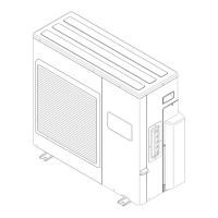
3. 1. Selecting an installation location
WARNING
Securely install the outdoor unit at a location that can withstand the weight of the unit.
Otherwise, the outdoor unit may fall and cause injury.
Be sure to install the outdoor unit as prescribed, so that it can withstand earthquakes
and typhoons or other strong winds. Improper installation can cause the unit to topple
or fall, or other accidents.
Do not install the outdoor unit near the edge of a balcony. Otherwise, children may
climb onto the outdoor unit and fall off of the balcony.
CAUTION
Do not install the outdoor unit in the following areas:
• Area with high salt content, such as at the seaside. It will deteriorate metal parts,
causing the parts to fail or the unit to leak water.
• Area lled with mineral oil or containing a large amount of splashed oil or steam,
such as a kitchen. It will deteriorate plastic parts, causing the parts to fail or the
unit to leak water.
• Area that generates substances that adversely affect the equipment, such as
sulfuric gas, chlorine gas, acid, or alkali. It will cause the copper pipes and brazed
joints to corrode, which can cause refrigerant leakage.
• Area containing equipment that generates electromagnetic interference. It will
cause the control system to malfunction, preventing the unit from operating
normally.
• Area that can cause combustible gas to leak, contains suspended carbon bers or
ammable dust, or volatile inframmables such as paint thinner or gasoline. If gas
leaks and settles around the unit, it can cause a re.
• Area that has heat sources, vapors, or the risk of the leakage of ammable gas in
the vicinity.
• Area where small animals may live. It may cause failure, smoke or re if small
animals enter and touch internal electrical parts.
• Area where animals may urinate on the unit or ammonia may be generated.
Please install the outdoor unit without slant.
Install the outdoor unit in a well-ventilated location away from rain or direct sunlight.
If the outdoor unit must be installed in an area within easy reach of the general public,
install as necessary a protective fence or the like to prevent their access.
Install the outdoor unit in a location that would not inconvenience your neighbors, as
they could be affected by the airow coming out from the outlet, noise, or vibration. If it
must be installed in proximity to your neighbors, be sure to obtain their approval.
If the outdoor unit is installed in a cold region that is affected by snow accumulation,
snow fall, or freezing, take appropriate measures to protect it from those elements. To
ensure a stable operation, install inlet and outlet ducts.
Install the outdoor unit in a location that is away from exhaust or the vent ports that
discharge vapor, soot, dust, or debris.
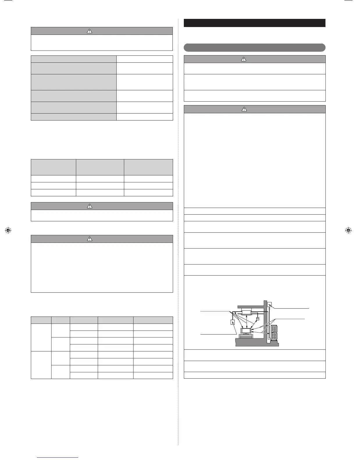
Install the indoor unit, outdoor unit, power supply cable, connection cable, and remote
control cable at least 40 in. (1 m) away from a television or radio receivers. The
purpose of this is to prevent TV reception interference or radio noise. (Even if they are
installed more than 40 in. (1 m) apart, you could still receive noise under some signal
conditions.)
Branch switch and
circuit breaker
Branch switch and
circuit breaker
40 in. (1 m) or more
40 in. (1 m) or more
If children under 10 years old may approach the unit, take preventive measures so
that they cannot reach the unit.
Keep the length of the piping of the indoor and outdoor units within the allowable
range.
For maintenance purposes, do not bury the piping.
2. 4. 6. Limitation of refrigerant piping length
CAUTION
The total maximum pipe lengths and height difference of this product are shown in the
table.
If the units are further apart than this, correct operation cannot be guaranteed.
Total max. length (a+b)
164 ft. (50 m)*
1
Max. length for each indoor unit
(a or b)
82 ft. (25 m)
Max. height difference between
outdoor unit and each indoor unit
(H1)
49 ft. (15 m)
Max. height difference between
indoor units (H2)
33 ft. (10 m)
Min. length for each indoor unit
(a or b)
16 ft. (5 m)
Total min. length (a+b)
49 ft. (15 m)
)
*1 If the total piping is longer than 98 ft. (30 m), additional refrigerant charging is neces-
sary. (For more information, refer to “6.2 Additional charging”.)
2. 4. 7. Selecting pipe sizes
The diameters of the connection pipes differ according to the capacity of the indoor unit.
Refer to the following table for the proper diameters of the connection pipes between the
indoor and outdoor units.
Capacity of indoor
unit
Gas pipe size
(thickness)
in. (in.) [mm (mm)]
Liquid pipe size
(thickness)
in. (in.) [mm (mm)]
7 – 12 ø3/8 (0.032) [ø9.52 (0.8)] ø1/4 (0.032) [ø6.35 (0.8)]
15, 18 ø1/2 (0.032) [ø12.70 (0.8)] ø1/4 (0.032) [ø6.35 (0.8)]
24 ø5/8 (0.039) [ø15.88 (1.0)] ø1/4 (0.032) [ø6.35 (0.8)]
CAUTION
Operation cannot be guaranteed if the correct combination of pipes, valves, etc., is not
used to connect the indoor and outdoor units.
2. 4. 8. Heat insulation around connection pipes requirements
CAUTION
Install heat insulation around both the gas and liquid pipes.
Failure to do so may cause water leaks.
Use heat insulation with heat resistance above 248 °F. (Reverse cycle model only)
In addition, if the humidity level at the installation location of the refrigerant piping is
expected to exceed 70%, install heat insulation around the refrigerant piping. If the
expected humidity level is 70-80%, use heat insulation that is 19/32 in. or thicker and if
the expected humidity exceeds 80%, use heat insulation that is 25/32 in. or thicker.
If heat insulation is used that is not as thick as specied, condensation may form on
the surface of the insulation. In addition, use heat insulation with heat conductivity of
0.045 W/(m·K) or less (at 68 °F).
Connect the connection pipes according to “4.1. Flare connection” in this installation
manual.
2. 4. 9. Operating range
Model
Temperature Indoor air intake Outdoor air intake
36 type
Cooling
Maximum 90 °F DB 115 °F DB
Minimum 65 °F DB 14 °F DB
Heating
Maximum 88 °F DB 75 °F DB
Minimum 60 °F DB 5 °F DB
24 type
18 type
Cooling
Maximum 90 °F DB 115 °F DB
Minimum 65 °F DB 14 °F DB
Heating
Maximum 88 °F DB 75 °F DB
Minimum 60 °F DB -15 °F DB
Indoor humidity about 80% or less
9374747153_IM.indb 5 2014/12/19 14:57:16
 Loading...