En-10
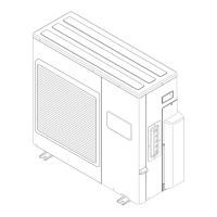
5. 3. Connection diagrams
36 type
1
2
3
1
2
3
G
G
G
1
2
3
1
2
3
G
G
1
2
3
1
2
3
G
1
2
3
G
L1
L2
1
2
3
G
G
INDOOR UNIT
OUTDOOR UNIT
INDOOR UNIT A
INDOOR UNIT B
INDOOR UNIT C
INDOOR UNIT D
TERMINAL
TERMINAL
UNIT A
UNIT B
UNIT C
UNIT D
TERMINAL
TERMINAL
TERMINAL
DISCONNECT SWITCH
(Locally purchased)
(Inter-unit)
Power lines
Grounding
line
208/230 V
208/230 V
208/230 V
208/230 V
208/230 V
208/230 V
208/230 V
208/230 V
208/230 V
208/230 V
208/230 V
208/230 V
Grounding
line
Grounding
line
Grounding
line
Power supply line
Single-phase, 208/230 V
DISCONNECT SWITCH
(Locally purchased)
DISCONNECT SWITCH
(Locally purchased)
DISCONNECT SWITCH
(Locally purchased)
24 type
1
2
3
1
2
3
G
G
G
1
2
3
1
2
3
G
G
G
1
2
3
1
2
3
G
L1
L2
INDOOR UNIT
OUTDOOR UNIT
INDOOR UNIT A
INDOOR UNIT B
INDOOR UNIT C
TERMINAL
TERMINAL
TERMINAL
DISCONNECT SWITCH
(Locally purchased)
DISCONNECT SWITCH
(Locally purchased)
DISCONNECT SWITCH
(Locally purchased)
TERMINAL
UNIT A
UNIT B
UNIT C
(Inter-unit)
Power lines
Grounding
line
208/230 V
208/230 V
208/230 V
208/230 V
208/230 V
208/230 V
208/230 V
208/230 V
208/230 V
Grounding
line
Grounding
line
Power supply line
Single-phase, 208/230 V
18 type
1
2
3
1
2
3
G
G
G
G
1
2
3
1
L1
2
3
L2
G
INDOOR UNIT
OUTDOOR UNIT
INDOOR UNIT A
INDOOR UNIT B
TERMINAL
TERMINAL
UNIT A
UNIT B
TERMINAL
DISCONNECT SWITCH
(Locally purchased)
(Inter-unit)
Power lines
Grounding
line
208/230 V
208/230 V
208/230 V
208/230 V
208/230 V
208/230 V
Power supply line
Single-phase, 208/230 V
DISCONNECT SWITCH
(Locally purchased)
WARNING
Disconnect switch for over current protection given in the table below is to be installed
between the indoor unit and the outdoor unit.
Disconnect switch
15A
CAUTION
Be sure to refer the above diagram and do correct eld wiring.
Wrong wiring causes malfunction of the unit.
Check local electrical codes and also any specic wiring instructions or limitation.
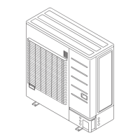
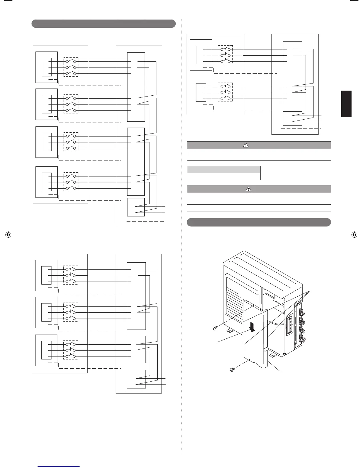
5. 4. Outdoor unit
(1) Service cover removal
• Remove the two mounting screws.
• Remove the service cover by pushing downwards.
Hook
(3 places)
Service cover
Direction of the service
panel removal
(2) Fasten the power supply cable and the connection cable to the conduit holder using
the lock nut.
(Open the knock out holes with the tool so as not to transform conduit plate if
necessary.)
(3) Connect the power supply cable and the connection cable to terminal.
(4) Fasten the power supply cable and connection cable with cable clamp.
9374747153_IM.indb 10 2014/12/19 14:57:20
 Loading...