SELECTING THE MOUNTING POSITION
Decide the mounting position with the customer as follows:
WARNING
Select installation locations that can properly support the weight of the indoor and outdoor units. Install the units
securely so that they do not topple or fall.
CAUTION
Do not install where there is the danger of combustible gas leakage.
Do not install the unit near heat source of heat, steam, or flammable gas.
If children under 10 years old may approach the unit, take preventive measures so that they cannot reach the
unit.
INDOOR UNIT
(1) Install the indoor unit on a place having a sufficient strength so that it withstand against the
weight of the indoor unit.
(2) The inlet and outlet ports should not be obstructed; the air should be able to blow all over
the room.
(3) Leave the space required to service the air conditioner.
(4) Install the unit where the drain pipe can be easily installed.
(5) Providing as much space as possible between the indoor unit and the ceiling will make work
much easier.
(For maintenance)
(1) Maintenance work of the control box is possible with the maintenance hole of the measure-
ment shown in the figure.
(2) If maintenance work is to be done from the bottom side, the maintenance hole needs to be
larger than the outside dimension of the indoor unit.
(3) If maintenance work is to be done from the top, keep the space of the more than 500 mm
between the indoor unit and ceiling.
450 mm
20 mm or more
(Service space)
450 mm
500 mm
Control box
CONNECTING PIPE REQUIREMENT
CAUTION
The maximum lengths of this product are shown in the following table. If the units are further apart than this,
correct operation can not be guaranteed.
CAUTION
Install heat insulation around both the gas and liquid pipes. Failure to do so may cause water leaks.
Use heat insulation with heat resistance above 120 °C. (Reverse cycle model only)
In addition, if the humidity level at the installation location of the refrigerant piping is expected to exceed 70%,
install heat insulation around the refrigerant piping. If the expected humidity level is 70-80%, use heat insulation
that is 15 mm or thicker and if the expected humidity exceeds 80%, use heat insulation that is 20 mm or thicker.
If heat insulation is used that is not as thick as specified, condensation may form on the surface of the insulation.
In addition, use heat insulation with heat conductivity of 0.045 W/(m·K) or less (at 20 °C).
• Use pipe with water-resistant heat insulation.
ELECTRICAL REQUIREMENT
• Always use H07RN-F or equivalent to the connection cord.
• Install all electrical works in accordance to the standard.
• Install the disconnect device with a contact gap of at least 3 mm in all poles nearby the units. (Both indoor unit and outdoor unit)
• Install the circuit breaker nearby the units.
• Electric wire size and breaker capacity:
30
Power supply cord (mm
2
)
MIN.
5.3
MAX.
13.3
Connection cord (mm
2
)
MAX.
3.5
MIN.
2.5
Breaker capacity (A)
Pipe outside diameter
Gas
15.88 mm (5/8 in.)
MAX.
70 m
Maximum height
(between indoor and outdoor)
30 m
Liquid
9.52 mm (3/8 in.)
MIN.
5 m
Pipe length
500 mm
Maintenance hole
INSTALLATION
PROCEDURE
1
INDOOR UNIT
INSTALLATION
WARNING
Install the air conditioner in a location which can
withstand a load of at least five times the weight
of the main unit and which will not amplify sound
or vibration.
If the installation location is not strong enough,
the indoor unit may fall and cause injuries.
If the job is done with the panel frame only, there
is a risk that the unit will come loose. Please take
care.
CAUTION
For installation, refer to the technical data.
RECOMMENDED RANGE OF
EXTERNAL STATIC PRESSURE
100Pa~250Pa
1. INSTALLING THE HANGERS
Hanging bolt installation diagram.
AIR
AIR
AIR
CAUTION
Fasten the unit securely with special nuts A and B.
2. LEVELING
Use the procedure in the following figure to adjust the levelness.
B
A
The side A of the unit with the drain port should be slightly lower
than the opposite side B of the unit. The height difference between
sides A and B should be from 0 to 20 mm.
3. MOUNTING THE DUCT
Follow the procedure in the following figure to install the ducts.
✽ Spacing between flange and drain pan.
CAUTION
If an intake duct is installed, take care not to dam-
age the temperature sensor (the temperature sen-
sor is attached to the intake port flange).
Be sure to install the air inlet grille and the air
outlet grille for air circulation. The correct tem-
perature cannot be detected. Grills must be in-
stalled so that man can’t touch unit fan, and can’t
be removed by only hand operation with tool.
Unit
Air Outlet Grille Air inlet Grille
(Room)
Be sure to install the air filter in the air inlet. If the
air filter is not installed, the heat exchanger may
be clogged and its performance may decrease.
Hanging bolt M10
(Obtained locally)
Special nut A
Washer
(Obtained
locally)
Special nut B
Hanger
400 mm
Level meter
865 mm
155 mm
585 mm
500 mm
1,080 mm
1,000 mm
1,050 mm
85 mm
Intake port flange
Outlet port flange
850 mm
325 mm
14 mm
✽ 14 mm
✽ 27 mm
26 mm
295 mm
4. INSTALLING THE DRAIN PIPES
Install the drain pipes according to the measurements given in
the following figure.
Flange position for connecting the drain pipes
CAUTION
This product has drain ports in two locations.
Follow the procedure in the figure to connect
drain pipes to each of them.
Be sure to properly insulate the drain pipes.
Use general hard polyvinyl chloride pipe (VP25) and connect it
with adhesive (polyvinyl chloride) so that there is no leakage.
Do not perform air bleeding.
Main drain pipe
Provide one trap on the main drain pipe near the indoor unit.
H
1
H
2
Safety drain
There is no need to provide a trap for the safety drain pipe. If
the safety drain pipe is connected to the main drain pipe,
make the connection below the trap on the main drain pipe.
• Once installation is complete, check the flow of the drain water.
129 mm
123 mm
41 mm
108 mm
208 mm
356 mm
371 mm
Safety drain pipe
ø25.4 mm (O.D.)
Main drain pipe
ø25.4 mm (O.D.)
Unit
Drain pipe (main)
Trap
H
1
= 100 mm (approx.)
H
2
= 50-100 mm
Unit
Drain pipe (main)
Drain pipe (safety)
2
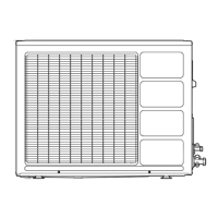
OUTDOOR UNIT
INSTALLATION
1. OUTDOOR UNIT PROCESSING
(1) Outdoor unit to be fasten with bolts at the four places indi-
cated by the arrows without fail.
(2) Fix securely with bolts on a solid block. (Use 4 sets of com-
mercially available M10 bolt, nut and washer.)
(3) Since the drain water flows out of the outdoor unit during
heating operation, install the drain pipe and connect it to an
commercial 16 mm hose.
(Reverse cycle model only)
(4) When installing the drain pipe, plug all the holes other than
the drain pipe mounting hole in the bottom of the outdoor unit
with putty so there is no water leakage.
(Reverse cycle model only)
CAUTION
When the outdoor temperature is 0°C or less, do
not use the accessory drain pipe and drain cap.
If the drain pipe and drain cap are used, the drain
water in the pipe may freeze in extremely cold
weather.
(Reverse cycle model only)
Drain pipe
mounting place
Bottom side
Drain cap
mounting place
4-ø12 mm hole
650 mm
Bolt
Block
370 mm
STANDARD PARTS
The following installation parts are furnished. Use them as required.
INDOOR UNIT ACCESSORIES
OPTIONAL PARTS
The following options are available.
•Long-life filter : UTD-LF60KA (P/N 9017230004).
• Simple remote controller : UTB-YPB (P/N 9077582006)
•Remote sensor : UTD-RS100 (P/N 9072619004)
• External control set : UTD-ECS5A (P/N 9077359004)
OUTDOOR UNIT ACCESSORIES
Application
For outdoor unit drain
piping work (May not be
supplied, depending on
the model.)
For filling in a gap at the
entrance of connection
cords.
Q’ty
1
2
1
Name and Shape
Drain pipe
Drain cap
Insulation (seal)
OUTDOOR UNIT
WARNING
Install the unit where it will not be tilted by more than 5˚.
When installing the outdoor unit where it may exposed to strong wind, fasten it securely.
(1) Install the outdoor unit in a location which can withstand the weight of the unit and vibration, and which can install horizontally.
(2) Provide the indicated space to ensure good airflow.
(3) If possible, do not install the unit where it will be exposed to direct sunlight.
(If necessary, install a blind that does not interfere with the airflow.)
(4) Do not install the unit near a source of heat, steam, or flammable gas.
(5) During heating operation, drain water flows from the outdoor unit.
Therefore, install the outdoor unit in a place where the drain water flow will not be obstructed. (Reverse cycle model only)
(6) Do not install the unit where strong wind blows or where it is very dusty.
(7) Do not install the unit where people pass.
(8) Install the outdoor unit in a place where it will be free from being dirty or getting wet by rain as much as possible.
(9) Install the unit where connection to the indoor unit is easy.
AIR
AIR
100 mm
or more
100 mm
or more
600 mm
or more
300 mm
or more
100 – 300 mm
*
250 mm or more
(Service space)
600 – 1000 mm
*
250 mm
or more
250 mm
or more
300 mm
or more
• When there are obstacles at the back side.
• When there are obstacles at the back and front sides.
• When there are obstacles at the back, side(s), and top.
• When there are obstacles at the back side with the installation of
more than one unit.
CONNECTING THE
PIPE
CAUTION
Do not use mineral oil on flared part. Prevent min-
eral oil from getting into the system as this would
reduce the lifetime of the units.
While welding the pipes, be sure to blow dry ni-
trogen gas through them.
The maximum lengths of this product are shown
in the table. If the units are further apart than this,
correct operation can not be guaranteed.
1. FLARING
(1) Cut the connection pipe to the necessary length with a pipe
cutter.
(2) Hold the pipe downward so that cuttings will not enter the pipe
and remove the burrs.
(3) Insert the flare nut (always use the flare nut attached to the
indoor and outdoor units respectively) onto the pipe and per-
form the flare processing with a flare tool.
Use the special R410A flare tool, or the conventional (for R22)
flare tool.
When using conventional flare tools to flare R410A pipes, the di-
mension A should be approximately 0.5 mm more than indicated in
the table (for flaring with R410A flare tools) to achieve the specified
flaring. Use a thickness gauge to measure the dimension A.
3
Width across flats
Check if [L] is flared uniformly
and is not cracked or scratched.
Die
A
Pipe
B
2. BENDING PIPES
The pipes are shaped by your hans. Be careful not to collapse them.
Do not bend the pipes in an angle more than 90°.
When pipes are repeatedly bend or stretched, the material will
harden, making it diffecult to bend or stretch them any more. Do not
bend or stretch the pipes more than three times.
CAUTION
To prevent breaking of the pipe, avoid sharp
bends.
Bend the pipe with a radius of curvature of 150
mm or over.
If the pipe is bent repeatedly at the same place, it
will break.
3. CONNECTION PIPES
Indoor unit
(1) Detach the caps and plugs from the pipes.
CAUTION
Be sure to apply the pipe against the port on the
indoor unit correctly. If the centering is improper,
the flare nut cannot be tightened smoothly. If the
flare nut is forced to turn, the threads will be dam-
aged.
Do not remove the flare nut from the indoor unit
pipe until immediately before connecting the con-
nection pipe.
(2) Centering the pipe against port on the indoor unit, turn the flare
nut with your hand.
To prevent gas leakage, coat the flare
surface with alkylbenzene oil (HAB).
Do not use mineral oil.
L
Pipe outside diameter
Dimension A (mm)
Flare tool for R410A, clutch type
6.35 mm (1/4 in.)
9.52 mm (3/8 in.)
12.70 mm (1/2 in.)
15.88 mm (5/8 in.)
19.05 mm (3/4 in.)
0 to 0.5
Pipe outside diameter Dimension B (mm)
6.35 mm (1/4 in.)
9.52 mm (3/8 in.)
12.70 mm (1/2 in.)
15.88 mm (5/8 in.)
19.05 mm (3/4 in.)
0
-0.4
9.1
13.2
16.6
19.7
24.0
Pipe outside
diameter
6.35 mm (1/4 in.)
9.52 mm (3/8 in.)
12.70 mm (1/2 in.)
15.88 mm (5/8 in.)
19.05 mm (3/4 in.)
17 mm
22 mm
26 mm
29 mm
36 mm
Width across flats
of Flare nut
(3) When the flare nut is tightened properly by your hand, use a
torque wrench to finally tighten it.
CAUTION
Hold the torque wrench at its grip, keeping it in the
right angle with the pipe, in order to tighten the flare
nut correctly.
Outdoor unit
Tighten the flare nut of the connection pipe at the outdoor unit
valve connector. The tightening method is the same as that as at
the indoor side.
Flare nut
Connection
pipe (liquid)
Connection
pipe (gas)
Flare nut
Holding spanner
Body side
Torque wrench
Flare nut
6.35 mm (1/4 in.) dia.
9.52 mm (3/8 in.) dia.
12.70 mm (1/2 in.) dia.
15.88 mm (5/8 in.) dia.
19.05 mm (3/4 in.) dia.
14 to 18 N·m (140 to 180 kgf·cm)
33 to 42 N·m (330 to 420 kgf·cm)
50 to 62 N·m (500 to 620 kgf·cm)
63 to 77 N·m (630 to 770 kgf·cm)
100 to 110 N·m (1000 to 1100 kgf·cm)
Tightening torque
Flare nut
Connection pipe
(liquid)
Connection pipe
(gas)
Flare nut
3-way valve
(liquid)
3-way valve
(gas)
4. VACUUM
(1) Remove the cap, and connect the gauge manifold and the
vacuum pump to the charging valve by the service hoses.
(2) Vacuum the indoor unit and the connecting pipes until the
pressure gauge indicates –0.1 MPa (–76 cmHg).
(3) When –0.1 MPa (–76 cmHg) is reached, operate the vacuum
pump for at least 60 minutes.
(4) Disconnect the service hoses and fit the cap to the charging
valve to the specified torque.
(5) Remove the blank caps, and fully open the spindles of the 2-
way and 3-way valves with a hexagon wrench [Torque: 6~7
N·m (60 to 70 kgf·cm)].
(6) Tighten the blank caps of the 2-way valve and 3-way valve to
the specified torque.
Tightening torque
20 to 25 N·m (200 to 250 kgf·cm)
20 to 25 N·m (200 to 250 kgf·cm)
25 to 30 N·m (250 to 300 kgf·cm)
30 to 35 N·m (300 to 350 kgf·cm)
35 to 40 N·m (350 to 400 kgf·cm)
10 to 12 N·m (100 to 120 kgf·cm)
Charging port cap
Blank
cap
6.35 mm (1/4 in.)
9.52 mm (3/8 in.)
12.70 mm (1/2 in.)
15.88 mm (5/8 in.)
19.05 mm (3/4 in.)
CAUTION
Do not purge the air refrigerants but use a
vacuum pump to vacuum the installation! There
is no extra refrigerant in the outdoor unit for air
purging!
Use a vacuum pump and gauge manifold and
charging hose for R410A exclusively. Using the
same vacuum for different refrigerants may
damage the vacuum pump or the unit.
Connecting pipe
Blank cap
Hexagon wrench
3-way valve
Charging port
Cap
Service hose
with valve core
Outdoor unit
Use a 4 mm
hexagon wrench.
Vacuum pump
Service hose
Gauge manifold
Nut
(Continued to the next page)
Drain pipe mounting hole
Base
Drain pipe
* If the space is larger than that is stated, the condition will
be the same as that there are no obstacles.
Duct Type
Indoor unit is an appliance not accessible to the general public.
For authorized service personnel only.
This mark indicates procedures which, if improperly performed, are most likely to result
in the death of or serious injury to the user or service personnel.
This mark indicates procedures which, if improperly performed, might lead to the death or
serious injury of the user.
This mark indicates procedures which, if improperly performed, might possibly result in
personal harm to the user, or damage to property.
DANGER
Never touch electrical components immediately after the power supply has been turned off. Electrical shock
may occur. After turning off the power, always wait 5 minutes or more before touching electrical components.
This air conditioner uses new refrigerant HFC (R410A).
The basic installation work procedures are the same as conventional refrigerant models.
However, pay careful attention to the following points:
Since the working pressure is 1.6 times higher than that of conventional refrigerant models, some of the
piping and installation and service tools are special. (See the table below.)
Especially, when replacing a conventional refrigerant model with a new refrigerant R410A model, always
replace the conventional piping and flare nuts with the R410A piping and flare nuts.
Models that use refrigerant R410A have a different charging port thread diameter to prevent erroneous
charging with conventional refrigerant and for safety. Therefore, check beforehand. [The charging port
thread diameter for R410A is 1/2 UNF 20 threads per inch.]
Be more careful that foreign matter (oil, water, etc.) does not enter the piping than with refrigerant models.
Also, when storing the piping, securely seal the openings by pinching, taping, etc.
When charging the refrigerant, take into account the slight change in the composition of the gas and liquid
phases, and always charge from the liquid phase side whose composition is stable.
Special tools for R410A
Copper pipes
It is necessary to use seamless copper pipes and it is desirable that the
amount of residual oil is less than 40 mg/10m. Do not use copper pipes having
a collapsed, deformed or discolored portion (especially on the interior sur-
face). Otherwise, the expansion valve or capillary tube may become blocked
with contaminants.
As an air conditioner using R410A incurs pressure higher than when using
conventional refrigerant, it is necessary to choose adequate materials.
Thicknesses of copper pipes used with R410A are as shown in the table.
Never use copper pipes thinner than that in the table even when it is available
on the market.
DANGER
WARNING
CAUTION
Contents of change
Pressure is high and cannot be measured with a conventional gauge. To prevent erroneous mixing
of other refrigerants, the diameter of each port has been changed.
It is recommended the gauge with seals –0.1 to 5.3 MPa (–76 cmHg to 53 kgf/cm
2
) for high pres-
sure. –0.1 to 3.8 MPa (–76 cmHg to 38 kgf/cm
2
) for low pressure.
To increase pressure resistance, the hose material and base size were changed.
A conventional vacuum pump can be used by installing a vacuum pump adapter.
Special gas leakage detector for HFC refrigerant R410A.
Tool name
Gauge manifold
Charge hose
Vacuum pump
Gas leakage detector
Thicknesses of Annealed Copper Pipes (R410A)
Thickness
0.80 mm
0.80 mm
0.80 mm
1.00 mm
1.20 mm
Pipe outside diameter
6.35 mm (1/4 in.)
9.52 mm (3/8 in.)
12.70 mm (1/2 in.)
15.88 mm (5/8 in.)
19.05 mm (3/4 in.)
SPLIT TYPE AIR CONDITIONER
INSTALLATION INSTRUCTION
SHEET
(PART NO. 9374693016)
CAUTION
Use a clean gauge manifold
and charging hose for
R410A exclusively.
Refrigerant
R410A
Name and Shape
Special nut A
(large flange)
Special nut B
(small flange)
Coupler heat
insulation
Coupler heat
insulation
Binder
Remote
controller
Tapping screw
(flush heads)
Remote controller cord
Q’ty
4
4
1
1
1
1
2
1
Application
For suspending the indoor
unit from ceiling
For indoor side pipe joint
(gas pipe)
For indoor side pipe joint
(liquid pipe)
For fixing the remote
controller cord
For installing the remote
controller
For connecting the remote
controller
(large)
(small)
9374693016B2front 04.12.14, 11:14 AM1
 Loading...