Do you have a question about the Fujitsu AS*9LSACW and is the answer not in the manual?
Details power source, frequency, running current, and input watts for different models.
Lists fan motor speeds (rpm) for indoor and outdoor units across various modes.
Provides physical dimensions (HxWxD) and gross/net weights for indoor and outdoor units.
Details noise levels (dB), maximum pipe length, and copper pipe thicknesses.
Specifies pipe length, full charge amount, and additional refrigerant details for R410A models.
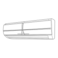
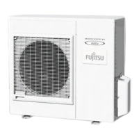
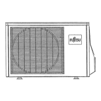
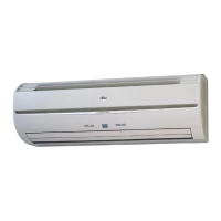
Shows diagrams and measurements for AS*9/12LSACW and AO*9/12LSAC indoor and outdoor units.
Displays diagrams and measurements for AS*9/12LSBCW and AO*9/12LFBC indoor and outdoor units.
Presents diagrams and measurements for AS*14/18LSBCW and AO*14/18LFBC indoor and outdoor units.
Illustrates the refrigerant flow and components for AS*9/12LSACW and AO*9/12LSAC models.
Shows the refrigerant circuit and flow for AS*9/12LSBCW and AO*9/12LFBC models.
Displays the refrigerant flow and circuit for AS*14/18LSBCW and AO*14/18LFBC models.
Provides the electrical circuit diagram for AS*9/12LSACW and AO*9/12LSAC indoor and outdoor units.
Shows the electrical wiring diagram for AS*9/12LSBCW and AO*9/12LFBC indoor and outdoor units.
Details the electrical circuit diagram for AS*14/18LSBCW and AO*14/18LFBC indoor and outdoor units.
Explains cooling capacity control, compressor frequency range, and limits based on temperature.
Details heating capacity control, compressor frequency range, and limits based on temperature.
Describes dry mode operation, compressor frequency, and indoor fan control.
Explains automatic mode switching based on temperature and operation zones.
Details fan speed settings for different modes and fan operation in AUTO mode.
Covers outdoor fan motor types and fan speed control based on compressor frequency.
Explains vertical louver and swing operation for air direction control.
Outlines compressor operation frequency ranges and start-up control sequences.
Details available timer settings (ON/OFF, Program, Sleep) and their operation.
Explains the control of the electronic expansion valve based on various sensor inputs.
Covers test operation, 3-minute restart prevention, and auto restart functions.
Describes manual unit operation and compressor preheating based on temperature.
Explains the coil-dry operation function and its settings.
Details conditions for starting and completing defrost operations for the outdoor unit.
Explains the automatic defrost operation when frost adheres to the outdoor heat exchanger.
Covers discharge gas temperature, current release, antifreezing, and cooling pressure protections.
Lists and describes essential tools and equipment required for handling R410A refrigerant.
Provides guidelines for pipe selection, flare nuts, and avoiding existing R22 piping.
Highlights differences in refrigerant oil and pressure compared to R22, and necessary precautions.
Explains the phase-out schedule of HCFC and the nature of HFC refrigerants.
Compares characteristics of R410A, R407C, and R22 refrigerants, including ODP and composition.
Presents data relating R410A condensing temperature to saturated pressure.
Discusses differences in oil, compressor, heat exchanger, and valves between R22 and R410A models.
Provides a flowchart and checks for when the unit does not operate at all.
Explains how to use the self-diagnosis function and interpret lamp displays for errors.
Lists error codes, their meanings, and diagnostic steps for various operational issues.
Details troubleshooting steps for IPM protection failures in the outdoor unit.
Outlines the procedure for diagnosing and resolving active filter failure errors.
Provides a table for diagnosing refrigerant cycle issues like leaks, compressor, EEV, and thermistor failures.
Explains jumper settings for indoor and outdoor units, including custom codes and auto-restart.
Shows curves for outdoor low pressure and total electric current vs. temperature for various models.
Displays curves for outdoor high pressure and total electric current vs. temperature for various models.
Provides tables and charts of thermistor resistance values versus temperature for various sensors.
Outlines critical points for R410A AC installation, including special tools and piping.
Guides on selecting appropriate indoor and outdoor unit mounting locations considering safety and airflow.
Covers outdoor unit mounting, connector installation, and the essential air purge procedure.
Details the process for cutting wall holes, installing the bracket, and forming drain hoses.
Explains how to connect piping, perform flaring, and wire the indoor and outdoor units.
Describes finishing touches like pipe insulation, sealing gaps, and performing a test run.
Specifies electrical requirements, power supply, wiring, and precautions for safe installation.
| Brand | Fujitsu |
|---|---|
| Model | AS*9LSACW |
| Category | Air Conditioner |
| Language | English |