- (01 - 20) -
WALL MOUNTED TYPE
ASU9-12RLF1
WALL MOUNTED TYPE
ASU9-12RLF1
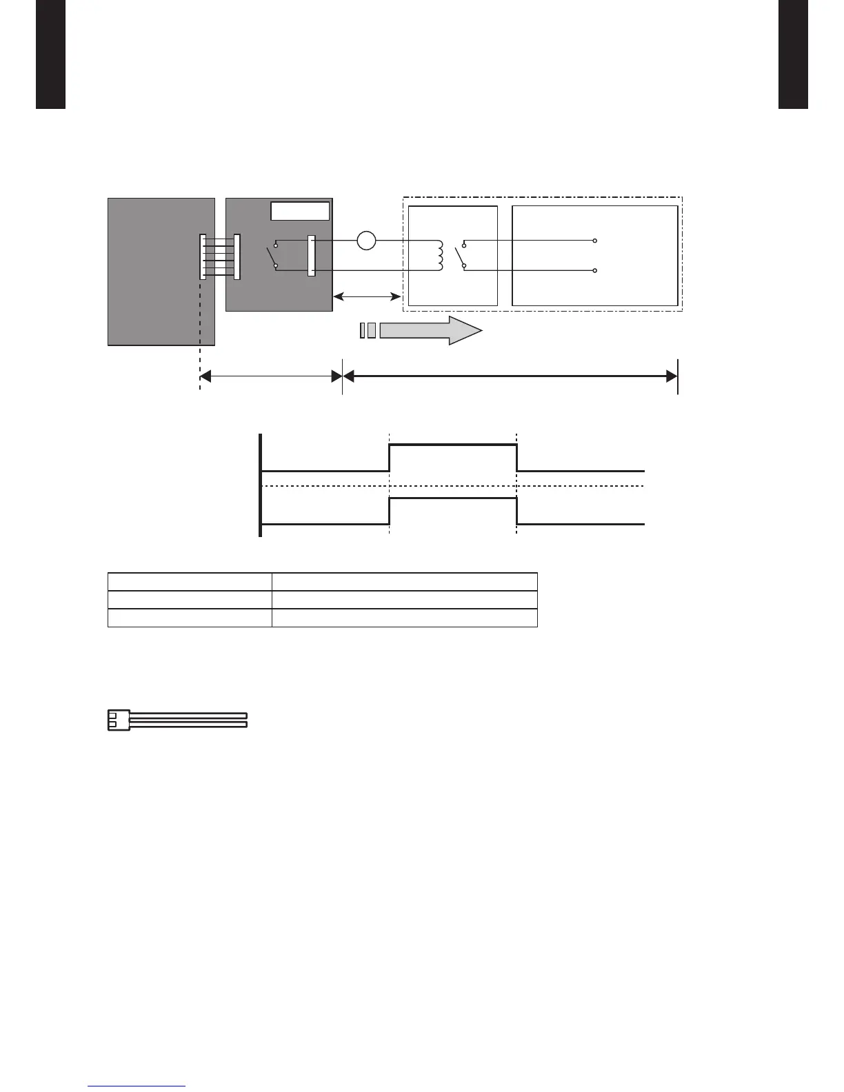
ERROR STATUS OUTPUT
An air conditioner error status signal can be output.
Circuit diagram example
z
*: Make the distance from the PC board to the connected unit within 33ft. (10m)
Relay spec.: Max. DC 24 V, 10 mA to less than 500 mA.
Parts (Optional)
z
Parts name
Model name
External connect kit UTY-XWZX Z5
Communication kit UTY-XCBXZ2
* For operating the EXTERNAL function, the wall mounted type requires the communication kit in addition to the wire
(UT Y-XWZX Z5).
Wire (External output) : UTY-XWZXZ5
 Loading...