En-13
9. ERROR CODES
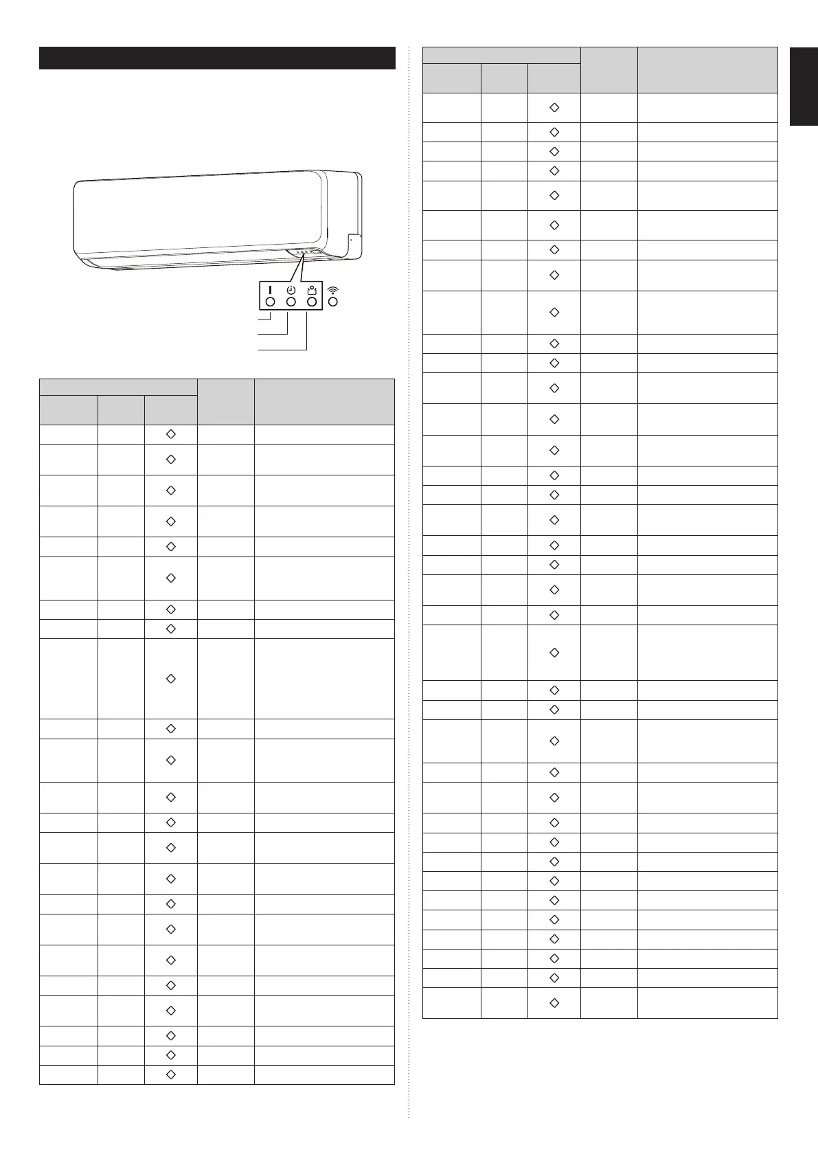
If you use a wireless remote controller, the lamp on the photo detector unit will output error
codes by way of blinking patterns. If you use a wired remote controller, error codes will ap-
pear on the remote control display. Refer to the lamp blinking patterns and error codes in
the table. An error display is displayed only during operation.
The error code table contains errors irrelevant to this product as well.
■
Error display on the indoor unit
LED1: OPERATION indicator lamp (green)
LED2: TIMER indicator lamp (orange)
LED3: ECONOMY indicator lamp (green)
* : For wired remote controller (optional)
Error display
Error code* Description
LED1
(green)
LED2
(orange)
LED3
(green)
(1)
(1)
11
Serial communication error
(1)
(2)
12
Wired remote controller
communication error
(1)
(5)
15
Check run unfinished Automatic
airflow adjustment error
(1)
(6)
16
Peripheral unit transmission PCB
connection error
(1)
(8)
18
External communication error
(2)
(1)
21
Unit number or Refrigerant
circuit address setting error
[Simultaneous multi-split type]
(2)
(2)
22
Indoor unit capacity error
(2)
(3)
23
Combination error
(2)
(4)
24
• Connection unit number
error (indoor secondary unit)
[Simultaneous multi-split type]
• Connection unit number error
(indoor unit or branch unit)
[Flexible multi-split type]
(2)
(6)
26
Indoor unit address setting error
(2)
(7)
27
Primary unit, secondary unit setup
error [Simultaneous multi-split
type]
(2)
(9)
29
Connection unit number error in
wired remote controller system
(3)
(1)
31
Power supply interruption error
(3)
(2)
32
Indoor unit PCB model information
error
(3)
(3)
33
Indoor unit motor electricity
consumption detection error
(3)
(5)
35
Manual auto switch error
(3)
(9)
39
Indoor unit power supply error for
fan motor
(3)
(10)
3A
Indoor unit communication circuit
(wired remote controller) error
(4)
(1)
41
Room temp. sensor error
(4)
(2)
42
Indoor unit heat ex. middle temp.
sensor error
(4)
(4)
44
Human sensor error
(5)
(1)
51
Indoor unit fan motor error
(5)
(3)
53
Drain pump error
Error display
Error code* Description
LED1
(green)
LED2
(orange)
LED3
(green)
●
(5)
●
(4)
54
Electric air cleaner reverse VDD
error
●
(5)
●
(5)
55
Filter set error
(5)
(7)
57
Damper error
●
(5)
●
(8)
58
Intake grille error
●
(5)
●
(9)
59
Indoor unit fan motor 2 error
(Left side fan)
●
(5)
●
(10)
5A
Indoor unit fan motor 3 error
(Right side fan)
(5)
(15)
5U
Indoor unit error
(6)
(1)
61
Outdoor unit reverse/missing
phase and wiring error
(6)
(2)
62
Outdoor unit main PCB
model information error or
communication error
(6)
(3)
63
Inverter error
(6)
(4)
64
Active filter error, PFC circuit error
(6)
(5)
65
• Trip terminal L error
• IPM temp error
(6)
(8)
68
Outdoor unit rush current limiting
resister temp. rise error
(6)
(10)
6A
Display PCB microcomputers
communication error
(7)
(1)
71
Discharge temp. sensor error
(7)
(2)
72
Compressor temp. sensor error
(7)
(3)
73
Outdoor unit Heat Ex. liquid temp.
sensor error
(7)
(4)
74
Outdoor temp. sensor error
(7)
(5)
75
Suction Gas temp. sensor error
(7)
(6)
76
• 2-way valve temp. sensor error
• 3-way valve temp. sensor error
(7)
(7)
77
Heat sink temp. sensor error
(8)
(2)
82
• Sub-cool Heat Ex. gas inlet
temp. sensor error
• Sub-cool Heat Ex. gas outlet
temp. sensor error
(8)
(3)
83
Liquid pipe temp. sensor error
(8)
(4)
84
Current sensor error
(8)
(6)
86
• Discharge pressure sensor error
• Suction pressure sensor error
• High pressure switch error
(9)
(4)
94
Trip detection
(9)
(5)
95
Compressor rotor position
detection error (permanent stop)
(9)
(7)
97
Outdoor unit fan motor 1 error
(9)
(8)
98
Outdoor unit fan motor 2 error
(9)
(9)
99
4-way valve error
(9)
(10)
9A
Coil (expansion valve) error
(10)
(1)
A1
Discharge temp. error
(10)
(3)
A3
Compressor temp. error
(10)
(4)
A4
High pressure error
(10)
(5)
A5
Low pressure error
(10)
(11)
AC
Heat sink temp error
(13)
(2)
J2
Branch boxes error
[Flexible multi-split type]
Display mode
●
: 0.5s ON / 0.5s OFF
◊
: 0.1s ON / 0.1s OFF
( ) : Number of flashing
9387603217-01_IM.indb 139387603217-01_IM.indb 13 20-Jul-21 16:06:2720-Jul-21 16:06:27
 Loading...