En-8
3.5.2. Remote controller custom setting
■ Custom code setting
By setting custom code of indoor unit and remote controller, you can specify the air condi-
tioner which the remote controller controls.
When two or more air conditioners are in the room and you wish to operate them sepa-
rately, set the custom code (4 selections possible).
NOTE: If custom codes is diff erent between the indoor unit and the remote controller,
the indoor unit cannot receive a signal from the remote controller.
How to set the remote controller custom code
(1) Press
until the indicators on the remote controller turn off .
(2) Press down [MODE] for more than 5 seconds.
The current custom code will be displayed (initially set to
).
(3) Press [TEMP./SELECT (
)] to change the
custom code between
A (
) ↔ B ( ) ↔ C ( / ) ↔ D ( ).
* Match the custom code on the display to the air
conditioner custom code.
(4) Press [MODE] again.
The custom code will be set.
The display will return to the original display.
• To change the air conditioner custom code, contact an authorized service
personnel (initially set to
).
• If you do not press any buttons for 30 seconds after the custom code is displayed,
the display returns to the original display. In this case, repeat the setting from step 2.
• Depending on the remote controller, the custom code may return to
when
replacing the batteries. In this case, reset the custom code as necessary. If you
do not know the air conditioner custom code, try each code until you fi nd the code
which operates the air conditioner.
4. OPTIONAL INSTALLATION WORK
CAUTION
• Before installing, be sure to disconnect all power supply.
• Do not touch the heat exchanger.
• When installing or removing parts of the air conditioner, be sure that the wire is not
caught by any parts or pulled hard. It may result in damage or malfunction of the air
conditioner.
• Connect the cable the circuit board.
CN65
CN47CN13
CN46
This air conditioner can be connected with the following optional kits. To install these op-
tional kits, the optional External input and output PCB box is necessary.
For details on how to install optional parts, refer to the installation manual included in
each item.
Connector No. Option type
CN13
Wired remote controller (via the Communication kit)
Simple remote controller (via the Communication kit)
CN46 External input
CN47 External output
CN65 External input and output PCB
4.1. Optional kit installation
NOTE:
When some wired remote controller is connected, the wireless remote controller cannot
be used.
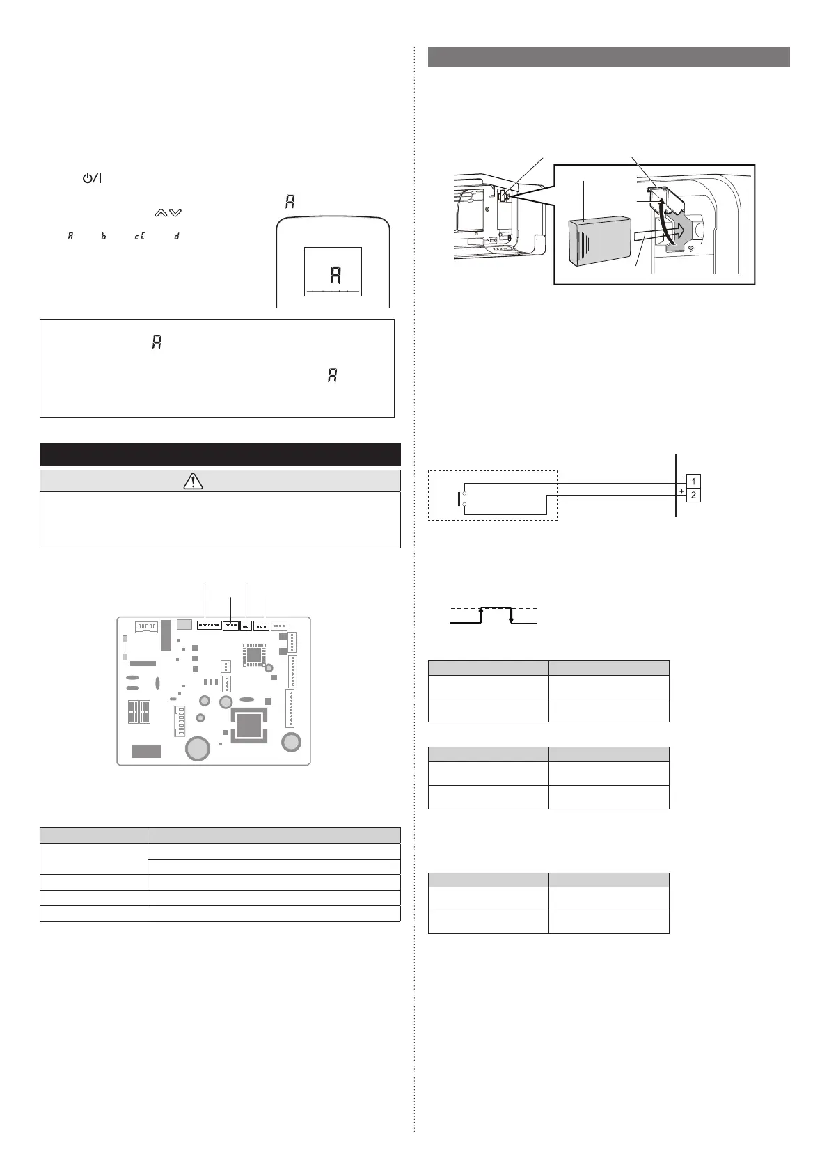
4.1.1. Installing the WLAN adapter
For installing the WLAN adapter, refer to the operation manual.
WLAN adapter cover
WLAN adapter
1. Open
2. Insert
4.1.2. External input and output
■
External input
• Indoor unit functions such as Operation/Stop or Forced stop can be done by using
indoor unit terminals.
• “Operation/Stop” mode or “Forced stop” mode can be selected with function setting of
indoor unit.
•
A twisted pair cable (22 AWG) should be used. Maximum length of cable is 492 ft. (150 m).
• Use an external input and output cable with appropriate external dimension, depending
on the number of cables to be installed.
• The wire connection should be separate from the power cable line.
● Dry contact terminal
When a power supply is unnecessary at the input device you want to connect, use the Dry
contact terminal.
*1
PCB
Connector
(CN46)
Connected device
*1: The switch can be used on the following condition: DC 12 V to 24 V, 1 mA to 15 mA.
Operation behavior
● Input signal type
Edge
ON
OFF
● When function setting is “Operation/Stop” mode 1.
Input signal Command
OFF → ON Operation
ON → OFF Stop
● When function setting is “Forced stop” mode.
Input signal Command
OFF → ON Forced stop
ON → OFF Normal
* When the forced stop is triggered, indoor unit stops and Operation/Stop operation by a
remote controller is restricted.
● When function setting is “Operation/Stop” mode 2.
Input signal Command
OFF → ON Operation
ON → OFF Stop (R.C. disabled)
NOTE: For details, refer to “
■ External input control” in “5.1. Function details”.
■
External output
• A twisted pair cable (22AWG) should be used. Maximum length of cable is 82 ft. (25 m).
• Use an external input and output cable with appropriate external dimension, depending
on the number of cables to be installed.
• Output voltage: Hi DC12V±2V, Lo 0V.
• Permissible current: 50mA
9387603217-01_IM.indb 89387603217-01_IM.indb 8 20-Jul-21 16:06:2620-Jul-21 16:06:26
 Loading...