En-4
Intake grille
Mounting
shaft
Mounting
shaft
■
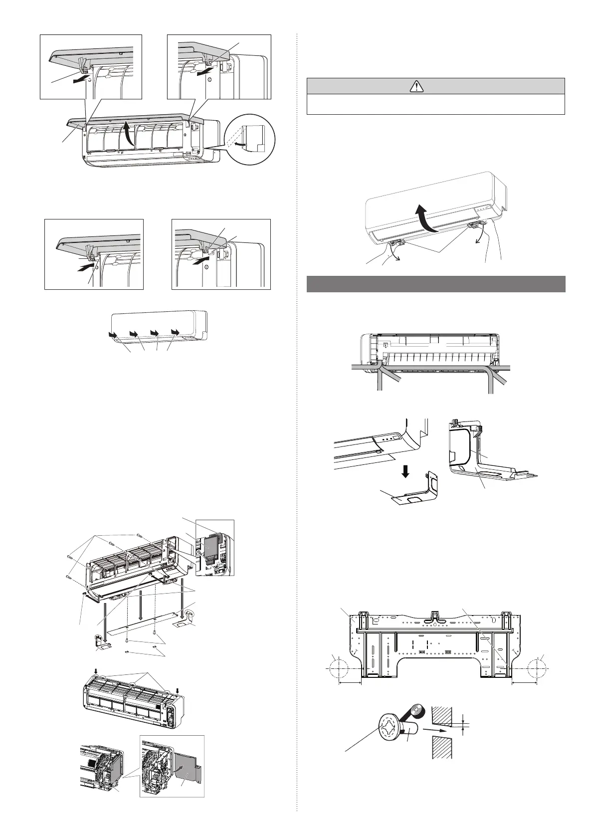
Intake grille installation
(1) Attach the left and right mounting shaft in the direction of the arrow to the panel top
bearing while supporting the intake grille horizontally. Press this until it clicks so that
each shaft snaps into place.
Mounting shaft
Mounting
shaft
Bearing
Bearing
(2) Press and close the intake grille.
Press here
3.2.2. Front panel / control cover removal and installation
* In this description, the intake grille and wire cover already has been removed.
When the wire cover A is removed, the wire cover B can be removed.
■
Front panel / control cover / under cover (L/R/C) removal
(1) Remove the under cover L/R.* (Press down on the markings on the side, then slide
down.)
* : If needed, remove the piping groove and make a necessary adjustment.
(2) Remove under cover C.
Remove the cap screws (2 places).
Remove the screws (2 places).
Pull down the center of the under cover C and remove it. **
** : If needed, remove the piping bracket (2 places).
(3) Remove the screw covers (2 places) on the bottom of the front panel, and then remove
the screws (4 places).
(4) Push down on the markings (2 places) on top of the front panel to release the hooks
(3 places), then pull the front panel towards you.
(5) Pinch the tab on the control cover to release the hook, then open.
Control cover
Screws (4 places)
Hook (3 places)
Markings (triangle)
Markings (triangle)
Markings (triangle)
Markings (triangle)
Screw covers
Tab
Under cover L
Wire cover B
Wire
cover A
Piping bracket (2 places)
Under cover C
Under cover R
Screws (2 places)
Cap screws (2 places)
■
Front panel / control cover / under cover (L/R/C) installation
Install the previous fi gure in reverse order.
* Be sure to attach the screws (4 places), screw cover(2 places) for front panel and screws
(2 places), cap screw (2 places) for under cover C.
CAUTION
Take caution when removing or installing the front panel. If the front panel falls, there
is a risk of injury.
3.2.3. Uninstalling the indoor unit
Remove the indoor unit from the wall hook bracket as follows.
(1) Put your fi ngers in the outer opening of the piping holder (A) in the fi gure.
While pushing down the piping holder (A), remove the hook from the wall hook
bracket (2 places).
(2) Pull the indoor unit towards you.
Piping
holder (A)
3.3. Pipe installation
3.3.1. Indoor unit piping direction
The piping can be connected in the
6
directions indicated in the following.
When the piping is connected to direction (B), (C), (D) or (E),
cut along the piping groove
on the side of the under cover with a hacksaw.
(B)
Right
outlet
(E) Left
outlet
(F) Left rear
outlet
(C) Right bottom
outlet
(A) Right rear outlet
(D) Left bottom
outlet
(Rear)
Under cover
Under cover (inside view)
Piping groove
3.3.2.
Cutting the hole in the wall for connecting the pipes
(1) Cut a 2-9/16 in (65 mm) diameter hole in the wall at the position shown in the
following.
(2) Cut the hole so that the outside end is lower ( 3/16 to 3/8 in [5 to 10 mm] ) than the
inside end.
(3) Always align the center of the wall hole. If misaligned, water leakage will occur.
(4)
Cut the wall pipe to match the wall thickness, stick it into the wall cap, fasten the cap with
vinyl tape, and stick the pipe through the hole.
(5) For the left piping and the right piping, cut the hole a little lower so that drain water
will fl ow freely.
Unit: in (mm)
Wall hook bracket
Centering marks
2-9/16
(65) hole
2-7/16 (62)
2-1/2 (64)
2-9/16
(65) hole
*Locally purchased
Wall
Fasten with
vinyl tape*
Wall cap*
Wall pipe*
(Inside)
(Outside)
3/16 to 3/8 (5 to 10) low
9387603217-01_IM.indb 49387603217-01_IM.indb 4 20-Jul-21 16:06:2620-Jul-21 16:06:26
 Loading...