En-9
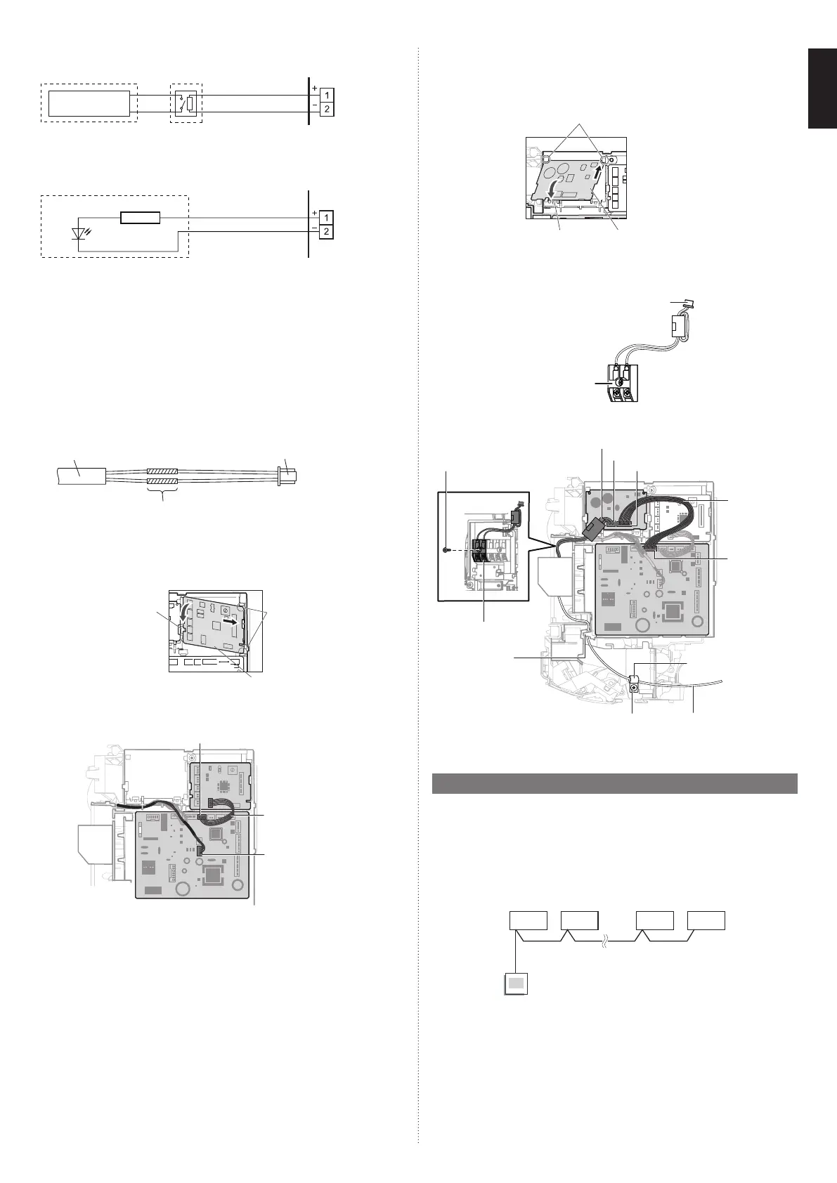
Output select
● When interlocking with external device
Connector
(CN47)
PCB
Connected
device
Relay (Locally purchased)
or
● When displaying “Operation/Stop”
Connector
(CN47)
PCB
Connected device
Resistor
LED
Operation behavior
*If function setting “60” is set to “00”, refer to “5. FUNCTION SETTING”.
■
Connection methods
Wire modifi cation
• Remove insulation from wire attached to wire kit connector.
• Remove insulation from locally purchased cable. Use crimp type insulated butt
connector to join fi eld cable and wire kit wire.
• Connect the wire with connecting wire with solder.
IMPORTANT: Be sure to insulate the connection between the wires.
Locally purchased
External connect kit (option)
Solder and insulate the connected parts.
4.1.3. Installing the External input/output PCB
(1) Remove the Intake grille, front panel, and control cover. Refer to “3.2. Removing and
replacing parts”.
(2) Insert the PCB to the clasps (2 places). Push the PCB down until the clasp on the
left is set.
Clasp
Clasps
(2 places)
External input/
output PCB
(3) Hook the WLAN adapter wire to the control box. Fix it with a cable tie.
Connector (CN65)
External input/
output PCB wire
Connector
(WLAN adapter wire)
(4) For the setting of rotary switch and DIP switch, refer to the installation manual of
optional parts.
NOTE: If the rotary switch on the “External input and output PCB” is set to “1”, function
number “46” will operate.
(5) Replace the control cover, front panel, and Intake grille.
(6) Refer to “5.1. Function details
■ External input control (Function number 46)” for
setting.
4.1.4. Installing the communication kit
(1) Remove the Intake grille, front panel, and control cover. Refer to “3.2. Removing and
replacing parts”.
(2) Insert the PCB to the clasps (2 places). Push the PCB down until the clasp on the
bottom is set.
Clasp
Communication PCB
Clasps
(3) Attach the terminal board to the indoor unit with 1 screw (accessory for option).
(4) Connect the connector of wire with EMI core to the communication PCB, then fi x it
with the cable tie (accessory for option).
Connector
Terminal block
(5) Connect the communication kit and main PCB.
(6) Connect the wired remote controller cable to the terminal block as shown in the fi gure.
Cable tie (accessory for option)
Connector (CN300)
Connector (CN301)
Screw (small, accessory for option)
Wire with
connector
(accessory
for option)
Connector
(CN13)
Cable clamp
(accessory for option)
Wired remote
controller cable
Screw (large,
accessory for option)
Terminal block
Tab
(7) Replace the control cover, front panel, and Intake grille.
4.2. Group control
NOTE: Group control cannot be used together with WLAN adapter.
4.2.1. Group control system
A number of indoor units can be operated at the same time using a single remote controller.
*When different types of indoor units (such as wall mounted type and cassette type,
cassette type and duct type, or other combinations) are connected using group control
system, some functions may no longer be available.
(1) Connect up to 16 indoor units in a system.
A
BCDE
I.U. I.U. I.U. I.U.
Remote
controller
A, B, C, D, E : Remote controller cable.
A+B+C+D+E ≤ 546.8 yd (500 m).
9387603217-01_IM.indb 99387603217-01_IM.indb 9 20-Jul-21 16:06:2720-Jul-21 16:06:27
 Loading...