En-3
2.5. Pipe requirement
CAUTION
Refer to the installation manual for the outdoor unit for description of allowable pipe length
and height diff erence.
Model Liquid pipe size <thickness> Gas pipe size <thickness>
07, 09, 12
Ø 1/4 in (Ø 6.35 mm)
<1/16 in (0.80 mm)>
Ø 3/8 in (Ø 9.52 mm)
<1/16 in (0.80 mm)>
15
Ø 1/4 in (Ø 6.35 mm)
<1/16 in (0.80 mm)>
Ø 1/2 in (Ø 12.70 mm)
<1/16 in (0.80 mm)>
CAUTION
Install heat insulation around both the gas and liquid pipes. Failure to do so may
cause water leaks.
Use heat insulation with heat resistance above 248 °F (120 °C). Reverse cycle model
only.
In addition, if the humidity level at the installation location of the refrigerant piping
is expected to exceed 70%, install heat insulation around the refrigerant piping. If
the expected humidity level is 70-80%, use heat insulation that is 3/4 in. (15 mm) or
thicker and if the expected humidity exceeds 80%, use heat insulation that is 13/16 in.
(20 mm) or thicker.
If heat insulation is used that is not as thick as specifi ed, condensation may form on
the surface of the insulation. In addition, use heat insulation with heat conductivity of
0.045 W/(m•K) or less (at [68 °F (20 °C)]).
2.6. Electrical requirement
The indoor unit is powered from the outdoor unit or branch box. Do not power indoor unit
from separate power source.
WARNING
Standard for electrical wiring and equipment diff ers in each country or region. Before you
start electrical working, confi rm related regulations, codes, or standards.
■
Cable specifi cation
Cable Cable size Remarks
Connection cable 14AWG
3 cable+Ground (earth),
1φ 208/230 V
Max. Cable Length: Limit voltage drop to less than 2%. Increase cable gauge if voltage
drop is 2% or more.
2.7. Optional parts
Refer to each installation manual for the method of installing optional parts.
Parts name Model No. Application
Wired remote controller (*1) (*2) UTY-RNR
Z
For air conditioner operation
(2-wired type)
Simple remote controller (*1)
UTY-RSR
UTY-RHR
External input and output PCB UTY-XCSXZ2
For control input/output port
External connect kit
UTY-XWZXZ5
UTY-XWZX
Communication kit UTY-TWRXZ2
For the installation of 2-wired
remote controller
WLAN adapter UTY-TFSXF1 For wireless LAN control
• Optional parts are subject to change without notice.
*1: Optional Communication kit (UTY-TWRXZ2) is necessary for installation.
*2: The wired remote controller (UTY-RNR
Z
) and the wireless controller cannot be
used simultaneously.
3. INSTALLATION WORK
3.1. Selecting an installation location
Decide the mounting position with the customer as follows:
(1) Install the indoor unit level on a strong wall which is not subject to vibration.
(2) The inlet and outlet ports should not be obstructed: the air should be able to blow all
over the room.
(3)
Install the unit a dedicated electrical branch circuit.
(4)
Do not install the unit where it will be exposed to direct sunlight.
(5)
Install the unit where connection to the outdoor unit or branch box is easy.
(6) Install the unit where the drain pipe can be easily installed.
(7) Take servicing, etc. into consideration and leave the spaces shown in “3.1.1.
Installation dimensions”. Also install the unit where the fi lter can be removed.
Correct initial installation location is important because it is diffi cult to move unit after it is
installed.
WARNING
Install the air conditioner in a location which can withstand a load of at least 3 times the
weight of the main unit and which will not amplify sound or vibration. If the installation
location is not strong enough, the indoor unit may fall and cause injuries.
Withstandable weight (Unit weight x 3*)
66 lbs (30 kg)
*In accordance with UL standards.
CAUTION
• Do not install the unit in the following areas:
- Area with high salt content, such as at the seaside. It will deteriorate metal parts,
causing the parts to fail or the unit to leak water.
- Area fi lled with mineral oil or containing a large amount of splashed oil or steam, such
as a kitchen.
It will deteriorate plastic parts, causing the parts to fail or the unit to leak water.
- Area that generates substances that adversely aff ect the equipment, such as sulfuric
gas, chlorine gas, acid, or alkali.
It will cause the copper pipes and brazed joints to corrode, which can cause
refrigerant leakage.
- Area that can cause combustible gas to leak, contains suspended carbon fi bers or
fl ammable dust, or volatile infl ammables such as paint thinner or gasoline.
If gas leaks and settles around the unit, it can cause a fi re.
- Area where animals may urinate on the unit or ammonia may be generated.
• Do not use the unit for special purposes, such as storing food, raising animals,
growing plants, or preserving precision devices or art objects.
It can degrade the quality of the preserved or stored objects.
• Do not install where there is the warning of combustible gas leakage.
• Do not install the unit near a source of heat, steam, or fl ammable gas.
• Install the unit where drainage does not cause any trouble.
• Install the indoor unit, outdoor unit, branch box, power supply cable, connection
cable, and remote controller cable at least 40 in. (1m) away from a television or radio
receivers. The purpose of this is to prevent TV reception interference or radio noise.
(Even if they are installed more than 40 in. (1m) apart, you could still receive noise
under some signal conditions.)
• If children under 10 years old may approach the unit, take preventive measures so
that they cannot reach the unit.
• Install the indoor unit on the wall where the height from the fl oors more than 71 in.
(1.8 m).
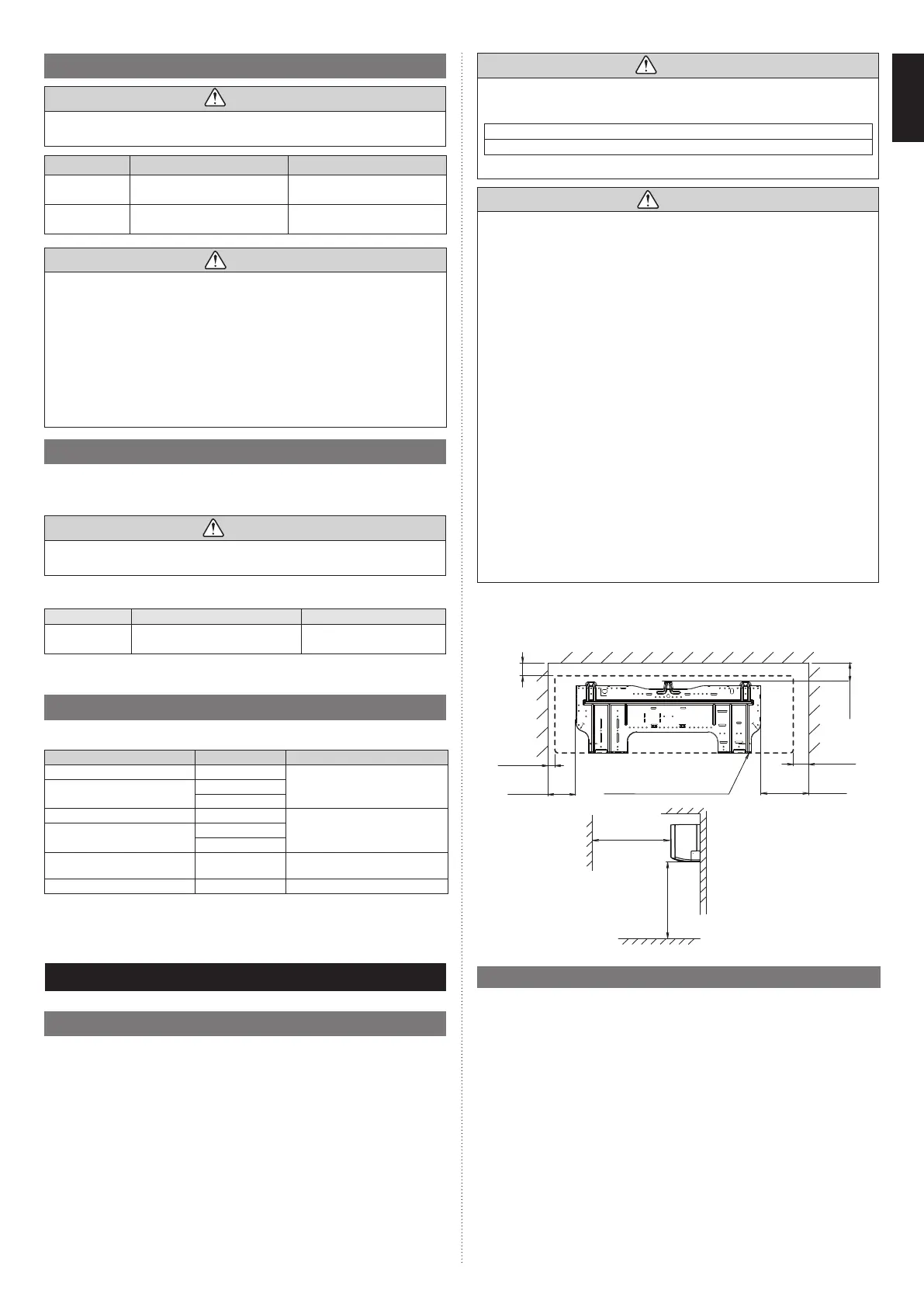
3. 1.1. Installation dimensions
Keep the distance between the wall hook bracket or indoor unit to the surrounding walls
as indicated in the following fi gure.
Wall hook bracket
Outline of the indoor unit
[ 1-15/16 (50)
or more ]
2-5/8 (67)
or more
[ 1-9/16 (40)
or more ]
[ 2-3/4 (70)
or more ]
4-3/16 (107)
or more
60 (1500)
or more
71 (1800) or more
Unit: in (mm)
7-3/16 (183)
or more
3.2. Removing and replacing parts
3.2.1. Intake grille removal and installation
■
Intake grille removal
(1) Hold the intake grille with both hands at the side, then pull to the front until it becomes
hooked.
(2) Keeping the intake grille in a horizontal position, pull the mounting shaft on the left and
right to release.
9387603217-01_IM.indb 39387603217-01_IM.indb 3 20-Jul-21 16:06:2620-Jul-21 16:06:26
 Loading...