12-2. External output
Use an external output cable with appropriate external dimension, depending on the number of ca-
bles to be installed.
¢
Operation status output
Indoor unit type Connector
Wall mounted ASU7RLF1, ASU9RLF1, ASU12RLF1, ASU15RLF1 CNB01
Floor AGU9RLF, AGU12RLF, AGU15RLF CN20
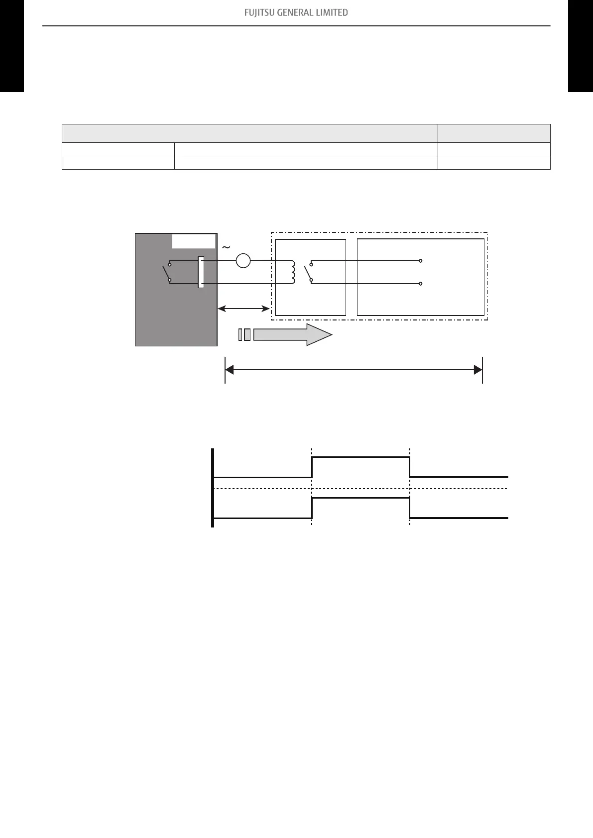
Air conditioner operation status signal can be output.
• Circuit diagram example
Locally purchased
Indoor unit
control PCB*1
Connected unit
Example: Display
Example: Relay unit
Relay
power supply
DC 24 V
1
2
Signal
V
Connector
33 ft
(10 m)*2
– *1: PCB of communication kit is used for wall mounted type (ASU7RLF1, ASU9RLF1,
ASU12RLF1, and ASU15RLF1).
– *2: Make the distance from the PCB to the connected unit within 33 ft (10 m).
– Relay spec: Max. DC 24 V, 10 mA to less than 500 mA.
On
Off
Operation
Stop
Indoor unit
Output signal
- 123 -
12-2. External output 12. External input and output (RLF1 series wall mounted type and floor type indoor unit)
MULTI-SPLIT TYPE
5-unit type
MULTI-SPLIT TYPE
5-unit type
 Loading...