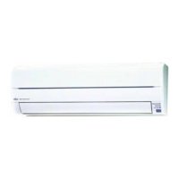
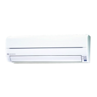
OUTDOOR UNIT
OUTDOOR UNIT INSTALLATION
WARNING
1 Install the unit where it will not be tilted by more than 3˚. However, do not install the unit with it tilted towards the side
containing the compressor.
2 When installing the outdoor unit where it may exposed to strong wind, fasten it securely.
(1) Outdoor unit to be fasten with bolts at the four places indicated by the
arrows without fail.
(2) Fix securely with bolts on a solid
block. (Use 4 sets of commercially
available M10 bolt, nut and
washer.)
P/N 9315342027-01
FINISHING
(1) Insulate between pipes.
● For rear, right, and bottom piping, overlap the connection pipe heat insulation and
indoor unit pipe heat insulation and bind them with vinyl tape so that there is no gap.
● For left and left rear piping and center piping, butt the connection pipe heat insulation
and indoor unit pipe heat insulation together and bind them with and vinyl tape so that
there is no gap.
● For left and left rear piping and center piping, wrap the area which accommodates the
rear piping housing section with cloth tape.
● For left and left rear piping and center piping, bind the connection cord to the top of the
pipe with vinyl tape.
● For left and left rear piping and center piping, bundle the piping and drain hose to-
gether by wrapping them with cloth tape over the range within which they fit into the
rear piping housing section.
(2) Temporarily fasten the connection cord along the connection pipe with vinyl tape. (Wrap
to about 1/3 the width of the tape from the bottom of the pipe so that water does not enter.)
(3) Fasten the connection pipe to the outside wall with saddles, etc.
(4) Fill the gap between the outside wall pipe hole and the pipe with sealer so that rain
water and wind cannot blow in.
(5) Fasten the drain hose to the outside wall, etc.
Pipe
(Saddle)
(Outside wall cap)
(Sealer putty)
(Outdoors)
Left piping
Connection cord
Pipe
Drain hose
For connection from the left rear
Connection cord
Wall pipe
Connection
pipe
Check the following:
GOOD
Lifted up
Saddle
Wave End in water
Wall
Drain hose
BAD
BAD BAD
Drain hose
Pipe
Drain hose
Cloth tape
Wrap with
cloth tape
Overlap the insulation
Bind the pipes together so
that there is no gap.
Connection pipe
(heat insulation)
Vinyl tape
Indoor unit pipe
(heat insullation)
Transmitter section
Test run button
TEST RUNNING
● Perform test operation and check items 1 and 2 below.
● For the test operation method, refer to the operating manual.
● The outdoor unit, may not operate, depending on the room temperature. In this case, press the test run button on the remote control unit while
the air conditioner is running, (Point the transmitter section of the remote control unit toward the air conditioner and press the test run button
with the tip of a ball-point pen, etc.)
● To end test operation, press the remote control unit START/STOP button.
(When the air conditioner is run by pressing the test run button, the OPERATION indicator lamp and TIMER indicator lamp will simultaneously
flash slowly.)
1. INDOOR UNIT
(1) Is operation of each button on the remote control unit normal?
(2) Does each lamp light normally?
(3) Do the air flow-direction louver operate normally?
(4) Is the drain normal?
2. OUTDOOR UNIT
(1) Is there any abnormal noise and vibration during operation?
(2) Will noise, wind, or drain water from the unit disturb the neighbors?
(3) Is there any gas leakage?
(3) Since the drain water flows out of the outdoor unit during heating
operation, install the drain pipe and connect it to a commercial 16 mm
hose. (Reverse cycle model only)
(4) When installing the drain pipe, plug all the holes other than the drain
pipe mounting hole in the bottom of the outdoor unit with putty so
there is no water leakage. (Reverse cycle model only)
CAUTION
When the outdoor temperature is 0 °C or less, do not use
the accessory drain pipe and drain cap. If the drain pipe
and drain cap are used, the drain water in the pipe may
freeze in extremely cold weather. (Reverse cycle model only)
Drain pipe mounting hole
Base
Drain pipe
(1) Remove the cap, and connect the gauge manifold and the vacuum
pump to the charging valve by the service hoses.
(2) Vacuum the indoor unit and the connecting pipes until the pressure
gauge indicates –0.1 MPa (–76 cmHg).
(3) When –0.1 MPa (–76 cmHg) is reached, operate the vacuum pump
for at least 60 minutes.
(4) Disconnect the service hoses and fit the cap to the charging valve to
the specified torque.
(5) Remove the blank caps, and fully open the spindles of the 3-way valves
with a hexagon wrench [Torque: 6~7 N·m (60 to 70 kgf·cm)].
(6) Tighten the blank caps of the 3-way valve to the specified torque.
Bottom side
Drain cap
mounting place
Drain pipe
mounting place
650 mm
4-ø 12 hole
370 mm
Bolt
Nut
Block
AIR PURGE
CAUTION
(1) Do not purge the air with refrigerants, but use a
vacuum pump to vacuum the installation! There is
no extra refrigerant in the outdoor unit for air purging!
(2) Use a vacuum pump and gauge manifold and charg-
ing hose for R410A exclusively. Using the same
vacuum for different refrigerants may damage the
vacuum pump or the unit.
(3) After connecting the piping, check the all joints for
gas leakage with gas leak detector.
(4) When inspecting gas leakage, always use the
vacuum pump for pressure. Do not use nitrogen gas.
(5) When adding refrigerant, add the refrigerant from the
charging port at the completion of work.
(6) The maximum length of the piping is 50 m. If the units
are further apart than this, correct operation can not
be guaranteed.
20 to 25 N·m (200 to 250 kgf·cm)
30 to 35 N·m (300 to 350 kgf·cm)
10 to 12 N·m (100 to 120 kgf·cm)
Tightening torque
Blank
cap
9.52 mm (3/8 in.)
15.88 mm (5/8 in.)
Charging port cap
Connecting pipe
Blank cap
Hexagon wrench
3-way valve
Charging port
Cap
Service hose
with valve core
Outdoor unit
Use a 4 mm
hexagon wrench.
Gauge manifold
Service hose
Vacuum pump
CAUTION
Use a clean gauge mani-
fold and charging hose
for R410A exclusively.
t
Additional charge
Refrigerant suitable for a piping length of 20 m is charged in the
outdoor unit at the factory.
When the piping is longer than 20 m, additional charging is necessary.
For the additional amount, see the table below.
Between 20 m and 50 m, when using a connection pipe other than
that in the table, charge additional refrigerant with 40g/1 m as the
criteria.
Pipe length
Additional refrigerant
30 m
400 g
40 m
800 g
50 m
1200 g
ELECTRICAL WIRING (OUTDOOR UNIT)
(1) Service cover removal
• Remove the two mounting screws.
• Remove the service cover by pushing downwards.
(2) Valve cover removal.
• Remove the one mounting screw.
• Remove the valve cover by sliding upward.
(3) Connect the power supply cord and the connection cord to terminal.
(4) Fasten the power supply cord and connection cord with cord clamp.
(5) Power supply cord and connection cord should be fixed with cable
clip as shown in the figure.
Fill in a gap at the entrance of the cords with insulation (seal).
(6) Put the service cover and valve cover back after completion of the
work.
Power supply cord
or connection cord
30 mm
40 mm or more
Earth wire
Keep the earth wire longer than the other wires.
Power supply cord and
connection cord
Cable clip
Insulation
(Seal)
Direction of the service
panel removal
Service cover
Hook
(3 places)
Hook
(4 places)
Valve cover
Power supply cord
and connection cord
Gap
Valve (Gas)
CAUTION
When connecting the power supply cord, make sure that
the phase of the power supply matches with the phase of
the terminal board. If the phases do not match, the
compressor will rotate in reverse and will not be able to
compress.
Do not make power supply cord and connection cord come
in contact with valve (Gas).
WARNING
1 Before starting work, check that power is not being
supplied to the indoor unit and outdoor unit.
2 Match the terminal board numbers and connection
cord colors with those of the outdoor unit.
Erroneous wiring may cause burning of the electric
parts.
3 Connect the connection cords firmly to the terminal
board. Imperfect installation may cause a fire.
4 Always fasten the outside covering of the connection
cord with the cord clamp. (If the insulator is chafed,
electric leakage may occur.)
5 Always connect the ground wire.
Control box
Terminal
Power supply cord
Connection cord
(indoor unit and
outdoor unit
connection cord)
Cord
clamp

 Loading...