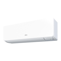
(Unit: mm)
1. 12V (Red)
2. Signal (White)
3. COM (Black)
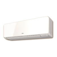
nsert a atbade screwdrier and reoe the ront case and rear case b twisting it sight.
Flat screwdriver
Front case
Hooks (2 places)
Rear case
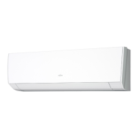
3) Install the rear case to the wall, box, etc. with 2 screws (M4 × 16 mm). Fix the 2 screws in
either horizontal or vertical position.
B. When the cable is along the wall:
Mount the rear case on the wall.
Cut off a hole for cabling in the front case.
Front case
Cut off
A. When mounting on the box:
Attach the case after leading the cable.
Screws
Box
Remote controller cable
Rear case
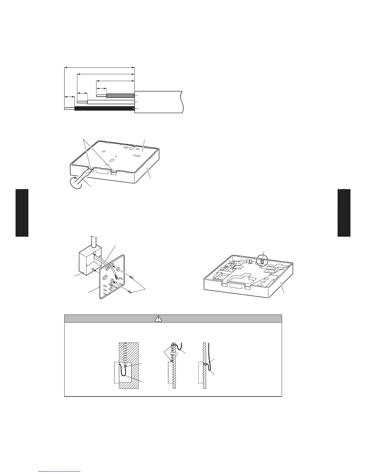
CAUTION
When connecting the remote controller cable, take measures to prevent water or insects
coming into the remote controller through the cable, such as to provide a trap or close the
hole for cabling with putty.
Putty
Putty
Putty
Trap
Trap
Trap
4) Setting up the DIP switch. Refer to "6. SYSTEM DESIGN".
- (05 - 10) -
CONTROL
SYSTEM
CONTROL
SYSTEM
 Loading...