6. SYSTEM DESIGN
PEAK CUT MODE
Operation that suppressed the current value can be performed by means of the following on-
site work.
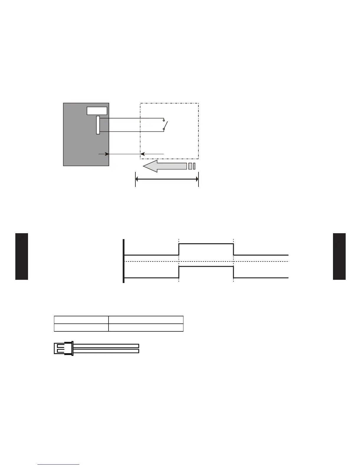
The air conditioner is set to the Peak cut mode when closing the contact input of a
commercial ON/OFF switch to a connector on the outdoor control PC board.
Circuit diagram example
* Make the distance from the PC board to the connected unit within 10 m.
Contact capacity: DC 24 V or more, 10 mA or more.
Use the following parts and construct a circuit as shown above.
nput igna Pea cut ode nput igna ora operation
*Set the "Peak cut mode" level, refer to "5. FUNCTION SETTING".
ON
OFF
ON
OFF
Input Signal
Peak cut mode
Parts (Optional)
Parts name External connect kit
Model name UTY-XWZ X Z3
Outdoor unit
control PC board
Connector
1
2
Signal
Field supply
*10 m
Connected unit
Ex.) Switch
- (06 - 107) -
SYSTEM
DESIGN
SYSTEM
DESIGN
 Loading...