Do you have a question about the Fujitsu ASYG12KGTB and is the answer not in the manual?
Specifies the types of multi-split systems covered by the manual.
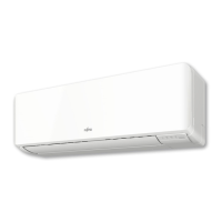
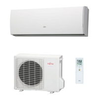
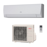
Lists and illustrates the available indoor unit models.
Technical specifications for various indoor unit types.
Detailed specifications for the compact cassette indoor unit series.
Detailed specifications for the mini duct indoor unit series.
Detailed specifications for the slim duct indoor unit series.
Detailed specifications for medium static pressure duct type indoor units.
Detailed specifications for wall-mounted indoor units.
Detailed specifications for ceiling type indoor units.
Detailed specifications for floor type indoor units.
Information on setting up and using wireless LAN control features.
Lists the necessary components and standards for wireless LAN control.
Provides dimensional drawings and data for various indoor unit types.
Detailed dimensions for compact cassette indoor units.
Detailed dimensions for mini duct indoor units.
Detailed dimensions for slim duct indoor units.
Detailed dimensions for medium static pressure duct type indoor units.
Detailed dimensions for wall-mounted indoor units.
Detailed dimensions for ceiling type indoor units.
Detailed dimensions for floor type indoor units.
Electrical wiring diagrams for various indoor unit types.
Wiring diagram for compact cassette indoor units.
Wiring diagrams for mini duct and slim duct indoor units.
Wiring diagrams for medium static pressure duct type indoor units.
Wiring diagrams for wall mounted indoor units.
Wiring diagram for ceiling type indoor units.
Wiring diagram for floor type indoor units.
Airflow patterns and temperature distribution charts.
Air velocity and temperature distribution for compact cassette types.
Air velocity and temperature distribution for mini duct types.
Air velocity and temperature distribution for slim duct types.
Air velocity and temperature distribution for wall mounted types.
Air velocity and temperature distribution for ceiling type units.
Air velocity and temperature distribution for floor type units.
Performance curves related to fan speed and static pressure.
Fan performance curves for mini duct type units.
Fan performance curves for slim duct type units.
Fan performance curves for medium static pressure duct type units.
Tables listing airflow rates for various models and conditions.
Noise level curves for different operating conditions and models.
Noise level curves for compact cassette type units.
Noise level curves for mini duct type units.
Noise level curves for slim duct type units.
Noise level curves for medium static pressure duct type units.
Noise level curves for wall mounted type units.
Noise level curves for ceiling type units.
Noise level curves for floor type units.
Diagrams showing measurement points for sound levels.
Electrical specifications for indoor units.
Details on protective devices and their operation.
Information on external control interfaces and connections.
External input/output details for specific indoor unit types.
External input/output details for specific indoor unit types.
External input/output details for specific wall mounted types.
External input/output details for specific wall mounted types.
External input/output details for specific wall mounted types.
External input/output details for floor type units.
Information on adjusting various operational functions.
DIP switch settings for mini and slim duct indoor units.
DIP switch settings for medium static pressure duct types.
Procedures for setting functions using wireless remote controllers.
Procedures for setting functions using wired remote controllers.
Procedures for setting functions using simple remote controllers.
Detailed explanation of available function settings.
Details on the UTY-RNNYM wired remote controller settings.
Details on the UTY-RVNYM wired remote controller settings.
Details on the UTY-RLRY wired remote controller settings.
Details on the UTY-RNRYZ* wired remote controller settings.
Details on the UTY-RSNYM simple remote controller settings.
Lists optional parts and accessories for indoor units.
Accessories specific to compact cassette indoor units.
Accessories specific to mini duct indoor units.
Accessories specific to slim duct indoor units.
Accessories specific to medium static pressure duct type units.
Accessories specific to wall mounted indoor units.
Accessories specific to ceiling type indoor units.
Accessories specific to floor type indoor units.
Lists optional parts for various configurations.
Overview of available wireless and wired remote controllers.
Information on the cassette grille accessory.
Lists other optional parts like filters, converters, and adapters.
Technical specifications for the AOYG30KBTA4 outdoor unit.
Dimensional drawings of the AOYG30KBTA4 outdoor unit.
Requirements for safe and efficient outdoor unit installation.
Installation space requirements for the AOYG30KBTA4 outdoor unit.
Diagram showing the refrigerant flow path.
Refrigerant circuit diagram for the AOYG30KBTA4 outdoor unit.
Electrical wiring schematic for the outdoor unit.
Wiring diagram for the AOYG30KBTA4 outdoor unit.
Tables showing cooling and heating capacities for combinations.
Tables detailing various indoor unit combinations and their capacities.
Cooling capacity data based on varying temperatures.
Heating capacity data based on varying temperatures.
Factors affecting capacity based on pipe length and height.
Compensation rates for AOYG30KBTA4 based on installation variables.
Guidelines for calculating additional refrigerant charge.
Refrigerant charge calculation for AOYG30KBTA4 based on pipe length.
Airflow rates for cooling and heating modes.
Airflow specifications for the AOYG30KBTA4 outdoor unit.
Noise level curves and measurement points.
Graphs showing noise levels across different frequencies.
Diagrams illustrating sound level measurement positions.
Electrical specifications for the outdoor unit.
Information on built-in safety mechanisms.
Settings for outdoor unit functions.
How to adjust function settings using DIP switches and push buttons.
Details on the optional low noise operation function.
Information on controlling current limits.
Procedures for checking and testing the system.
Steps for performing the check run and interpreting results.
Procedures for conducting a test run.
List of error codes and their meanings.
Procedure for pump-down operation, essential for refrigerant handling.
Lists available accessories for the outdoor unit.
Accessories specific to the AOYG30KBTA4 outdoor unit.
Important guidelines for installing the outdoor unit safely and correctly.
Locations to avoid for outdoor unit installation due to safety or performance concerns.
Key considerations and countermeasures for proper outdoor unit installation.
Technical specifications for the AOYG36KBTA5 outdoor unit.
Dimensional drawings of the AOYG36KBTA5 outdoor unit.
Requirements for safe and efficient outdoor unit installation.
Installation space requirements for the AOYG36KBTA5 outdoor unit.
Diagram showing the refrigerant flow path.
Refrigerant circuit diagram for the AOYG36KBTA5 outdoor unit.
Electrical wiring schematic for the outdoor unit.
Wiring diagram for the AOYG36KBTA5 outdoor unit.
Tables showing cooling and heating capacities for combinations.
Tables detailing various indoor unit combinations and their capacities.
Cooling capacity data based on varying temperatures.
Heating capacity data based on varying temperatures.
Factors affecting capacity based on pipe length and height.
Compensation rates for AOYG36KBTA5 based on installation variables.
Guidelines for calculating additional refrigerant charge.
Refrigerant charge calculation for AOYG36KBTA5 based on pipe length.
Airflow rates for cooling and heating modes.
Airflow specifications for the AOYG36KBTA5 outdoor unit.
Noise level curves and measurement points.
Graphs showing noise levels across different frequencies.
Diagrams illustrating sound level measurement positions.
Electrical specifications for the outdoor unit.
Information on built-in safety mechanisms.
Settings for outdoor unit functions.
How to adjust function settings using DIP switches and push buttons.
Details on the optional low noise operation function.
Information on controlling current limits.
Procedures for checking and testing the system.
Steps for performing the check run and interpreting results.
Procedures for conducting a test run.
List of error codes and their meanings.
Procedure for pump-down operation, essential for refrigerant handling.
Lists available accessories for the outdoor unit.
Accessories specific to the AOYG36KBTA5 outdoor unit.
Lists optional parts for various configurations.
Important guidelines for installing the outdoor unit safely and correctly.
Locations to avoid for outdoor unit installation due to safety or performance concerns.
Key considerations and countermeasures for proper outdoor unit installation.
| Brand | Fujitsu |
|---|---|
| Model | ASYG12KGTB |
| Category | Air Conditioner |
| Language | English |