En-13
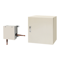
When connected to Apply voltage terminals of multiple DX-kits with a connected unit, be sure to
make a branch outside the DX-kit using a pull box, etc. as shown on below example.
Power supply
DC 12 to 24 V
Load
resistance
Load
resistance
connected unit
Input
device 2
Control unitControl unit Control unit
Input
device 1
Terminal
board
P.C.B.
CNA01
CNA01
CNA01
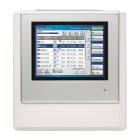
● Dry contact terminal ([CNA02], [CNA04] ,[CNA07])
When a power supply is unnecessary at the input device you want to connect, use the Dry
contact terminal ([CNA02], [CNA04], [CNA07]).
Control unit
Terminal
board
P.C.B.
*d
*d
*d
*c
Ch 4
*c
Ch 3
*c
Ch 1
*c
Ch 2
GND
CNA02
CNA04
CNA07
connected unit
*c Select very low current use contacts (usable at DC12V, DC1mA or less).
*d The wiring is different from Apply voltage terminals. Be suffi ciently careful when wiring.
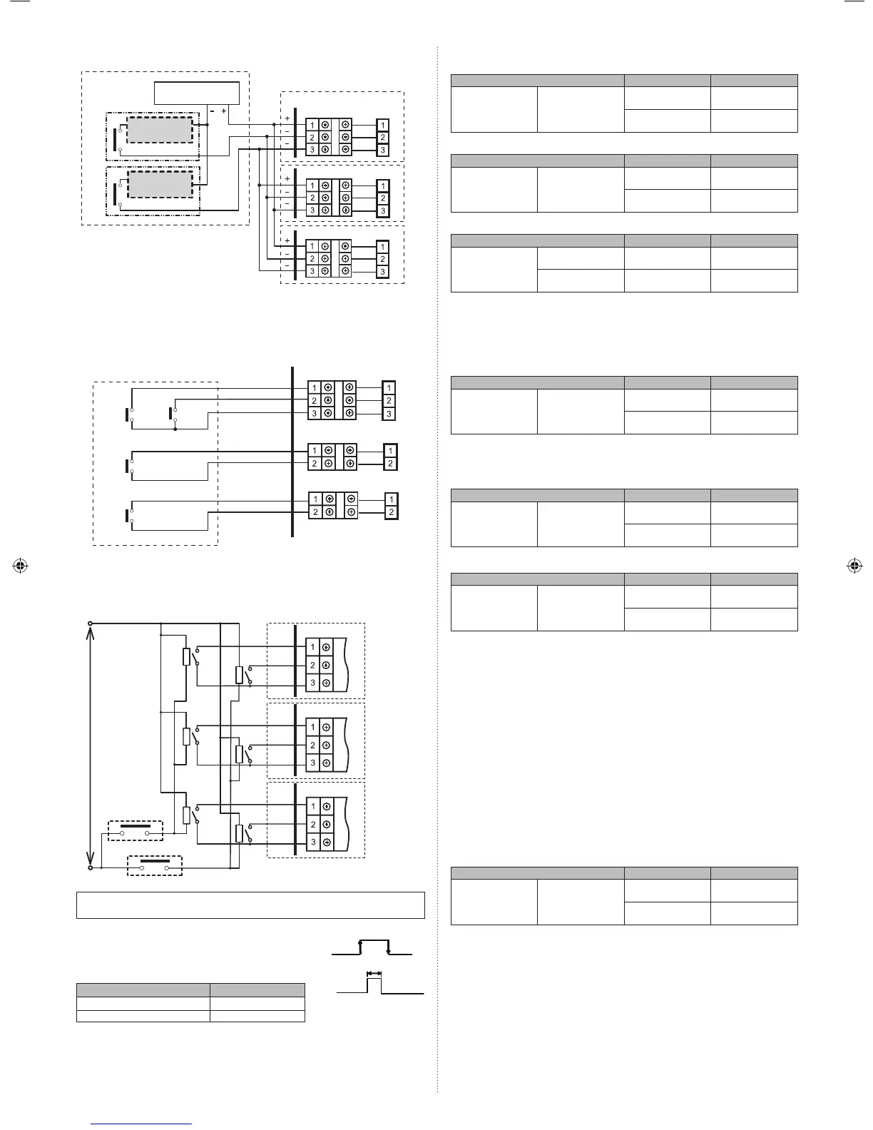
When connected to Dry contact terminals of multiple indoor units with a connected unit,
insulate each indoor unit with relay, etc. as shown on below example.
Power supply for relay
Control unit
Control unit
Control unit
Input device 2
Input device 1
K1 - K6: Relay
(Device for DC Current)
P.C . B
K1
P.C . B
P.C . B
K2
K3
K4
K5
K6
NOTE :
When connected to multiple indoor units directly, it will cause breakdown.
Operation behavior
● Input signal type
The input signal type can be selected.
It is switched by DIP switch on the indoor unit PCB.
Pulse
The width of pulse
must be longer than
200m sec.
Edge
DIP switch [Set 2 -2] Input signal type
OFF (Factory setting) Edge
ON Pulse
(1) ON/OFF SIGNAL (INPUT)
[For the “Edge” input method, function settings “60”=00]
Terminal block Input signal Command
ON/OFF SIGNAL
(INPUT)
Pin1 to Pin3
OFF → ON Operation
ON → OFF Operation stopped
[For the “Edge” input method, function settings “60”=01]
Terminal block Input signal Command
ON/OFF SIGNAL
(INPUT)
Pin1 to Pin3
OFF → ON Cooling operation
ON → OFF Operation stopped
[For the “Pulse” input method]
Terminal block Input signal Command
ON/OFF SIGNAL
(INPUT)
Pin1 to Pin2 OFF → ON Operation
Pin1 to Pin3 OFF → ON Stop
* The last command has priority.
* The indoor units within the same remote controller group operates in the same mode.
(2) ERROR SIGNAL (INPUT)
If an error signal is input, perform protection operation (Thermostat OFF mode).
Make sure to install so that the input signals during normal operation is always “ON”.
Terminal block Input signal Command
ERROR SIGNAL
(INPUT)
Pin1 to Pin2
ON Normal
OFF Error
(3) COOL/HEAT SIGNAL
Switch the operation mode (heating/cooling).
[“Edge” input method, function settings “60”=00]
Terminal block Input signal Command
COOL/HEAT
SIGNAL
Pin1 to Pin2
OFF → ON Heat
ON → OFF Cool
[“Edge” input method, function settings “60”=01]
Terminal block Input signal Command
COOL/HEAT
SIGNAL
Pin1 to Pin2
OFF → ON Heating operation
ON → OFF Operation stopped
Note
• In heat recovery system, HEAT/COOL switching during operation is disabled unless the
RB unit and DX-kit are connected in 1-to-1.
• If switching the operation mode directly from cooling to heating to cooling, set the
priority mode to “indoor unit priority” (*1), and set the DX-kit to “Administrative indoor
unit(or Master indoor unit) (*2)”. Making this setting when the DX-kit and the VRF for
another indoor unit are connected to the same refrigerant system will make the DX-kit
prioritize the operation mode, so be careful.
*1) For the setting methods, refer to the installation manual for the outdoor unit in V-II and
J-II systems, and refer to the installation manual for the RB unit in VR-II system.
*2) For the settings method, see the wired remote controller installation manual and this
installation manual.
(4) FLOAT SW SIGNAL
Check the drain status.
If the “ON” status continues for 3 mins. or more, decide a drainage error, and perform a
protection stop. (Thermostat OFF and FAN OFF mode) Further, turn OFF and ON the
power again to restore.
[“Edge” input only]
Connector Input signal Command
FLOAT SW SIGNAL Pin1 to Pin3
OFF → ON Protection operation
ON → OFF Normal
9381279005_IM.indb 139381279005_IM.indb 13 6/30/2014 11:31:18 AM6/30/2014 11:31:18 AM
 Loading...