En-14
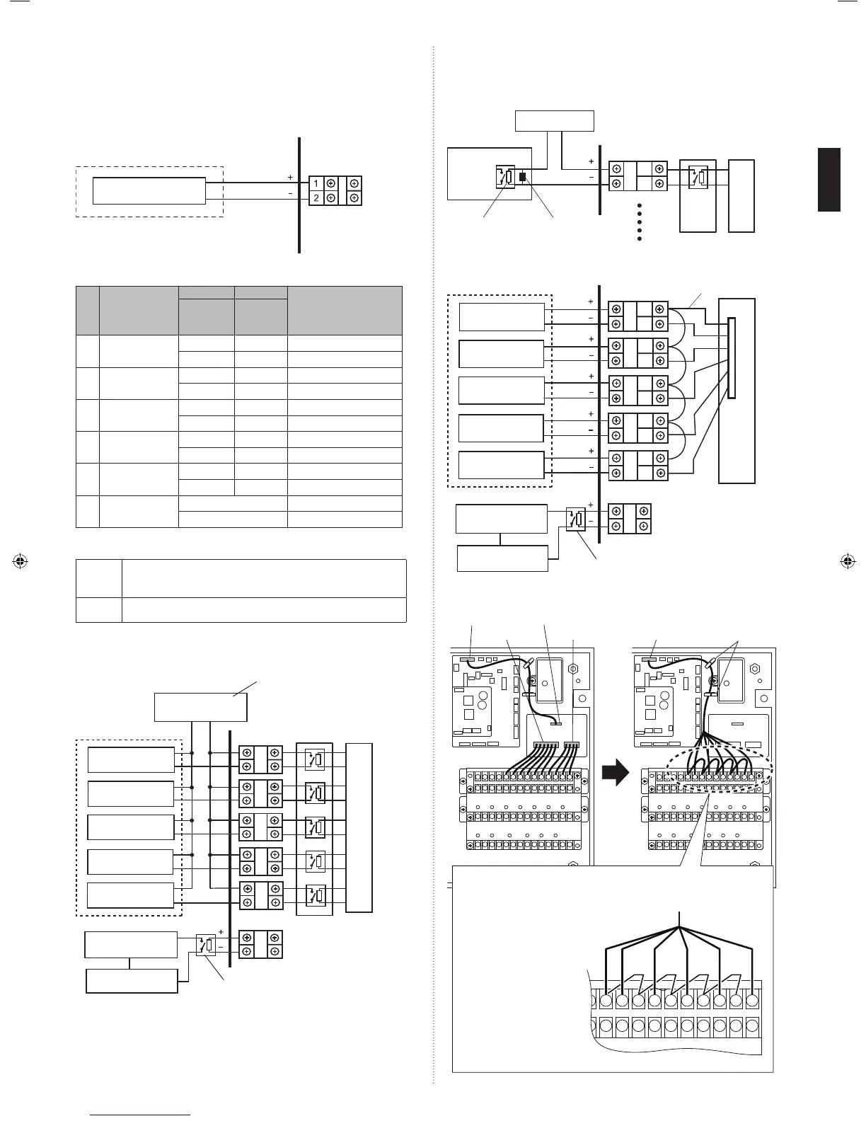
7.5.2. Analog external inputs
Changing the voltage of the signals entered to “analog external inputs” enables you to set
either the operation temperature or the required operation performance.
If using this function, make the following DIP switch settings.
i) Set the “Analog external inputs ON/OFF” setting to “ON”.
ii) Set the control item (either the operation temperature or required operation perfor-
mance).
Connected unit
Connected
device
Control unit
(DX-kit)
Analog signal
7.5.3. External output
No. Terminal block
Type-i Type-ii
Status
DX-kit
internal relay
status
DX-kit output
level
1 ON/OFF SIGNAL ON (Open) OFF Stop
OFF (Short) ON (DC12V) Operation
2 ERROR SIGNAL ON (Open) OFF Normal
OFF (Short) ON (DC12V) Error
3 FAN SIGNAL ON (Open) OFF FAN off
OFF (Short) ON (DC12V) FAN on
4 DEFROST SIGNAL ON (Open) OFF Normal
OFF (Short) ON (DC12V) Defrosting
5 THERMOSTAT
ON/OFF SIGNAL
ON (Open) OFF Thermostat Off
OFF (Short) ON (DC12V) Thermostat On
6 DRAIN PUMP
SIGNAL (*1)
OFF Drain pump Off
ON (AC 230 V) Drain pump On
● Select either of the following two power supply methods.
(Factory setting is Type-i)
Type-i • Using a power supply from other than the DX-kit (Connected unit, etc.)
• Usable tolerance voltages and currents: AC 220 to 240 V /1A max or
DC 30 V max /1A Max
Type-ii • Using a power supply from the DX-kit control unit
• Output voltage: Hi DC12V±2V, Lo 0 V / 50 mA max
• Use an external input and output cable with appropriate external dimension, depending
on the number of cables to be installed.
(1) Type-i: Using a power supply from other than the DX-kit (Connected unit, etc.)
1
2
3
4
5
6
Power supply
Terminal
Relay PC
board
Control unit (DX-kit)
Connected unit
Connected
device 1
Connected
device 2
Connected
device 3
Connected
device 4
Connected
device 5
Drain pump
PC board
Power supply
for drain pump
AC 220 to 240 V / 1A max
DC 30 V max / 1A max
When using a drain pump, connect relay that is
compatible with AC power supply. (fi eld supply)
• Precautions for Type-i
32
33
1
If connecting a dielectric load such as a relay
coil, etc., to the connected device, make sure to
add a surge protector circuit to the load side as
shown in the diagram.
Power supply
Connected device
Relay
Dielectric load
Surge protector circuit
Control unit (DX-kit)
Terminal
Relay PC
board
PC board
(2) Type-ii: Using a power supply from the DX-kit control unit
32
33
34
35
40
41
38
39
36
37
5
1
4
3
2
6
Terminal 12 VDC line
Control unit (DX-kit)
Connected unit
Connected
device 1
Connected
device 2
Connected
device 3
Connected
device 4
Connected
device 5
Drain pump
PC board
CNB01
Power supply
for drain pump
When using a drain pump, connect relay that is
compatible with AC power supply. (fi eld supply)
• If Type-ii is selected, change the wiring as shown in the diagram. (All cables used are
enclosed.)
(a1)
(b) (c) (d) (e)
(a2)
(a3)
(a4)
(a5)
(a6)
41403938373635343332
(a)
About the cable name and cable color
(a) Connection cable 1:
(a1) Brown, (a2) Red
(a3) Orange, (a4) Yellow
(a5) Green, (a6) Blue
(b) Connection cable 2:
Brown
(c) Connection cable 3:
Brown
(d) Connection cable 4:
Brown
(e) Connection cable 5:
Brown
CNB01 CN800
CN801 CN802 CNB01 Cable clamps
• If connecting an connection cables (accessories) to a terminal, make sure to
match the number of the label affi xed to the cable with the terminal number.
9381279005_IM.indb 149381279005_IM.indb 14 6/30/2014 11:31:18 AM6/30/2014 11:31:18 AM
 Loading...