3)Noteson Control Terminals:
A) Analog input terminal:
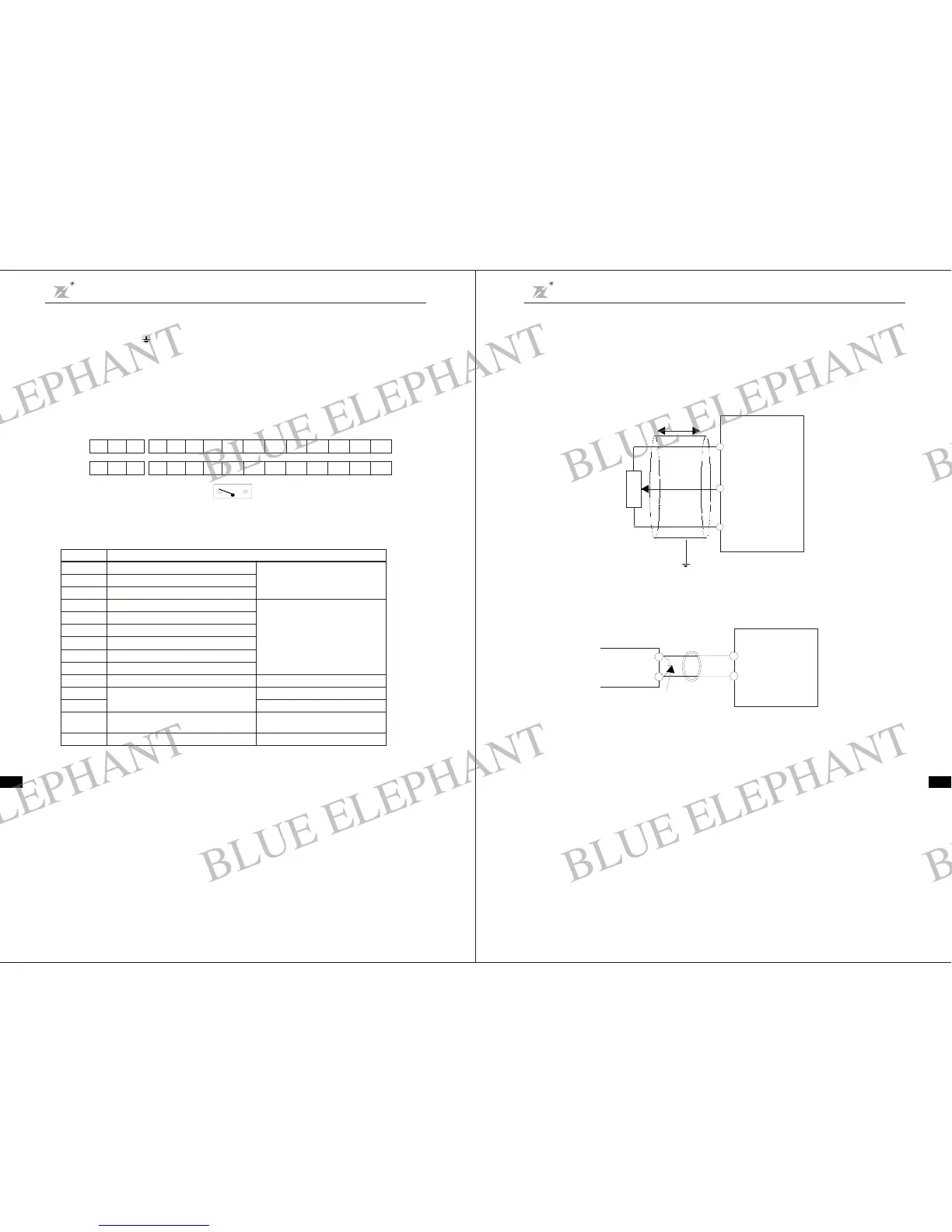
Si nce the weak analog voltagesignal is ea sily distur bed by e xternal d isturbance source, s hielded cabl e
sha llbe used and the cable shall be as sho rt a s possible and the l e ngt h sh a ll not exce ed 20m, a s shown in
the figur e 3-6:
If the ana log signa l is severe ly d istu rbed, filte r capaci tor o r ferr ite cor e s hall b e ins talle dat the anal o g
signa l sourc e as shown in the Fig. 3- 7:
Less than 20m
Potentionme t er
+10V
AI
ACM
DZB
AI
ACM
DZB
Ferrite c ore
Ex ternal ana log source
Wind 2 - 3 tu rns
0.022uF 5 0V、
C
Fig. 3 -6 An alog Inpu t Terminal of DZB Series I n verter
Fig.3 - 7 Analog I nput TerminalWi t h Filter d evices
B) Digital input t erminal :
The in ve rter j u d ges th e ON/OFF s ta tu s of these termin al s by r e ceiving t he digita l si gnal . H en ce, all th e
extern al contacto rs aretho se with h igh reliab ility of w eak signa l conduct ion.
Ifthe openco l lecto r is employ ed to provi de ON/OFF s ignal for the in vert er di g ital input terminal, then
it shal l b e consi dered that there iser ror opera tion c aused by power supp ly interfer ence .
Itisrecommendedtousecontactcontrolmode.
C) Digital Out put t ermina l :
Wh en digi tal out putt erminal dri ves a rel ay,the coil of therelay shall be install ed a snubbing diod e,
otherwise theDC 24V power supply m ay be damaged.
-14-
E. Grounding Terminal :
Gr ounding Terminal must be connected to earth re liably a nd the grounding resi stance shallbe les s than
5 , othe rwi se theequipment may work abnormally or be damaged. D o not share the PE a nd neutral line
of the ma ins supply.
Ω
5. Con trolTerminals and W irin g
1 Layoutof Contro lTermina ls(Fig.3-4,Fig3-5)):
2 Functionof Control Terminals):
-13-
Cha pter3 Mecha nical andEle c trical Installa tion
DZB Series
Chapter 3 Mechan ical and Ele ctrical Installation
DZB Series
ABC
10 V
S1 S2 S3 S4 S5 S6 A C M
AI FM MO1 MCM
200M:
ABC
10V
S1 S2 S3 S4 A CM
AI FM MO1 MCM
200J: AC M
+12V
Analog input select switch
AVIACI
MO -MCM
1
A-B
B-C
S1-DCM
S2-DCM
S3-DCM
S4-DCM
S5-DCM
S6-DCM
AV I -ACM
FM- AC M
10V~ACM
Multi-function PHC outp ut1
Multi-function indication output contact
Multi-function indication output contact
Multi-function input 1
Multi-function input 2
Multi-function input 3
Multi-function input 4
Multi-function input 5
Multi-function input 6
Auxil iary control po wer source
Analogs ignal input
Analogs ignal output
Power suppl yfor s peed setting
Ref e r toF2.19 F2. 2 1~
Refert oF2.01 F2.06~
0~10 V(Max. output freq. ) Input
4~20mA/0 ~10V Output
Refer t oF2.22
+10V(20mAmax.outputcurrent)
Funct ionTer minal
+12V
ACI-ACM
4~20mA/0 ~10V Input
BLUE ELEPHANT
BLUE ELEPHANT
BLUE ELEPHANT
BLUE ELEPHANT
BLUE ELEPHANT
BLUE ELEPHANT
BLUE ELEPHANT
BLUE ELEPHANT
BLUE ELEPHANT
BLUE ELEPHANT
BLUE ELEPHANT
BLUE ELEPHANT
BLUE ELEPHANT
BLUE ELEPHANT
BLUE ELEPHANT
BLUE ELEPHANT
BLUE ELEPHANT
BLUE ELEPHANT
BLUE ELEPHANT
BLUE ELEPHANT
BLUE ELEPHANT
BLUE ELEPHANT
BLUE ELEPHANT
BLUE ELEPHANT